Electrophotographic photoreceptor and image-forming apparatus

a photoreceptor and photoreceptor technology, applied in the field of electrophotographic photoreceptors, can solve the problems of deterioration of various properties, low chargeability, and inability to achieve desired electric and image properties of obtained electrophotographic photoreceptors, etc., to achieve low residual potential, high chargeability, and high sensitivity

Inactive Publication Date: 2012-10-16
MITSUBISHI CHEM CORP
View PDF11 Cites 0 Cited by
  • Summary
  • Abstract
  • Description
  • Claims
  • Application Information

AI Technical Summary

Benefits of technology

[0026]According to the present invention, a photoreceptor having a high sensitivity, a low residual potential and a high chargeability can be provided, where fluctuation of these electric properties due to exposure to strong light is small, particularly, the charging stability affecting the image density is good and the durability is excellent. Also, the coating solution for the formation by coating used to form the photosensitive layer has excellent stability, and a high-performance image forming apparatus can be provided, which exhibits a high sensitivity in the region of 380 to 500 nm and particularly, uses an exposure means comprising a semiconductor laser or LED capable of emitting monochromatic light in that region is used.

Problems solved by technology
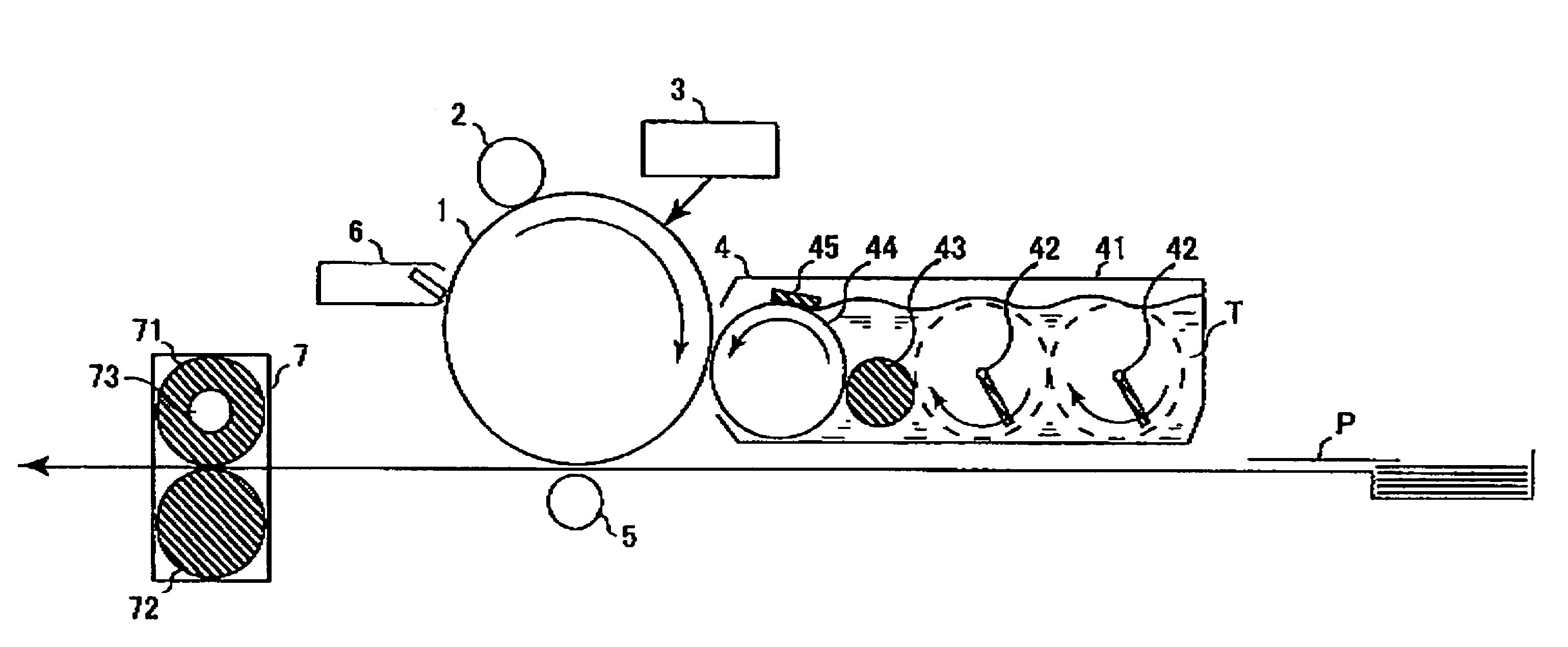
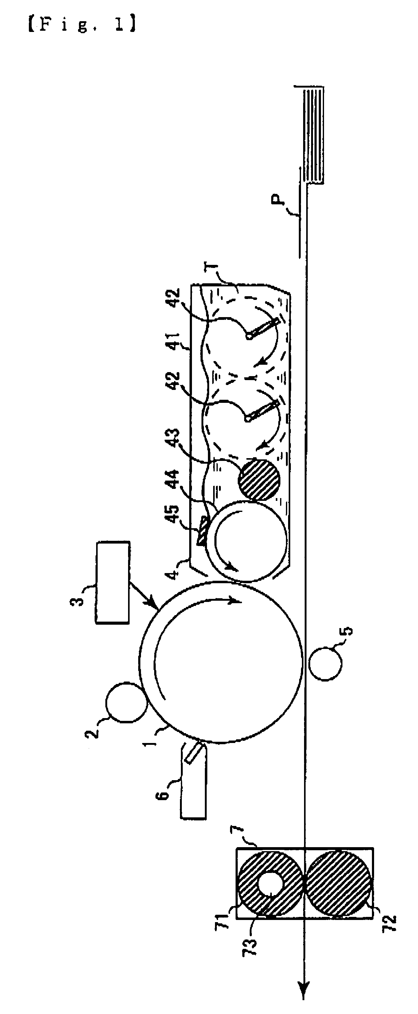
However, when such a conventionally known arylamine-based compound is used as the charge transport substance in the photosensitive layer of an electrophotographic photoreceptor and a coating solution obtained by dissolving or dispersing the charge transport substance in a solvent together with a binder resin or the like is coated and dried on an electroconductive support to form a photosensitive layer, there arises a problem that, for example, non-uniform dispersion with respect to the binder resin or crystal precipitation occurs in the photosensitive layer, as a result, the obtained electrophotographic photoreceptor can hardly have desired electric and image properties and at the same time, various properties are deteriorated by repeated use.
Also, the storage stability of the coating solution containing a compound having poor solubility in the solvent is bad, and crystal precipitation, serious increase of viscosity or separation of components is readily caused during storage.
Therefore, it has been difficult to industrially form a photosensitive layer containing such a compound by coating and drying the coating solution.
Furthermore, there is a problem that when the photoreceptor is incorporated into an image forming apparatus, the photoreceptor is exposed to exterior light at the maintenance of the image forming apparatus and thereby greatly damaged, and many charge traps are produced in the photoreceptor, giving rise to reduction in the photoreceptor performance.
Also, many of charge transport substances used at present in the organic photoreceptor have absorption for short-wavelength light and therefore, when such a charge transport substance is used in the photoreceptor to be exposed to short-wavelength light, this sometimes causes reduction of sensitivity or resolution.

Method used


Image

  • Electrophotographic photoreceptor and image-forming apparatus
  • Electrophotographic photoreceptor and image-forming apparatus
  • Electrophotographic photoreceptor and image-forming apparatus

Examples


example 1

[0146]A 75 μm-thick polyester film having vapor-deposited thereon aluminum was used as the support, and the following coating solution for charge generating layer was coated thereon by a wire bar to have a dry film thickness of 0.4 μm and dried to form a charge generating layer. On this layer, the following coating solution for charge transport layer was coated by an applicator and dried at room temperature for 30 minutes and then at 125° C. for 20 minutes to produce Photoreceptor A having a 25 μm-thick charge transport layer. The coating solution for charge transport layer used here was coated on a quartz glass to have a dry film thickness of 25 μm and dried, and the transmittance of the obtained sample for light at 427 nm was measured using a spectrophotometer UV1650PC manufactured by Shimadzu Corporation with the background being an equivalent quartz glass and found to be 99.9%.

[0147]Coating Solution for Charge Generating Layer

[0148]30 Parts of 1,2-dimethoxyethane was added to 1....

example 2

[0154]Photoreceptor B was produced in the same manner as in Example 1 except that in the coating solution for charge transport layer used Example 1, the amount of the compound represented by formula (7) was changed to 90 parts. The transmittance of the film for light at 427 nm was measured in the same manner as in Example 1 by using the coating solution for charge transport layer used here and found to be 99.9%.

example 3

[0155]Photoreceptor C was produced in the same manner as in Example 1 except that in the coating solution for charge transport layer used Example 1, the amount of the compound represented by formula (7) was changed to 50 parts. The transmittance of the film for light at 427 nm was measured in the same manner as in Example 1 by using the coating solution for charge transport layer used here and found to be 99.9%.


PUM

PropertyMeasurementUnit
wavelengthaaaaaaaaaa

Abstract

To provide an electrophotographic photoreceptor having a high sensitivity, a good balance of various electric properties such as chargeability and residual potential, a good stability of the coating solution, and an excellent light resistance.An electrophotographic photoreceptor comprising an electroconductive support having thereon a photosensitive layer, wherein the photosensitive layer contains a compound represented by the following formula (1):(wherein R1 represents a group having a chiral center, R2 represents a hydrogen atom, an alkyl group which may have a substituent, or an aryl group which may have a substituent, R3 and R4 each independently represents an alkylene group which may have a substituent, or an arylene group which may have a substituent, and R5, R6, R7 and R8 each independently represents an alkyl group which may have a substituent, or an aryl group which may have a substituent, and at least one member of R5 to R8 is an aryl group having a substituent).

Description

DETAILED DESCRIPTION OF THE INVENTION[0001]1. Technical Field to which the Invention Belongs[0002]The present invention relates to an electrophotographic photoreceptor. More specifically, the present invention relates to an electrophotographic photoreceptor which has a photosensitive layer containing an arylamine-based compound having a specific structure, particularly, an azo pigment-containing photosensitive layer, and which is suitably used by exposing it with monochromatic light at 380 to 500 nm.[0003]2. Background Art[0004]Recently, studies on an electrophotographic photoreceptor using an organic photoconductive substance for the photosensitive layer are proceeding and some of these photoreceptors have been put into practical use. The organic photoconductive substance is advantageous as compared with an inorganic substance, for example, in that the weight is light, the film formation and the production of a photoreceptor are easy, a transparent photoreceptor can be produced dep...

Claims


Application Information

Patent Timeline
Patent Type & Authority Patents(United States)
IPC IPC(8): G03G5/00
CPCG03G5/0614G03G5/0674G03G5/0679G03G5/0681G03G5/0687G03G5/0688G03G5/0696G03G5/06144G03G5/06
Inventor NAGAO, YUKAMITSUMORI, TERUYUKIHIROI, MASAYUKI
Owner MITSUBISHI CHEM CORP
Why Eureka
Try Eureka