Modular lamp for illuminating a hazardous underwater environment

a module lamp and hazardous underwater environment technology, applied in the field of illumination systems, can solve the problems of affecting the safety of maintenance personnel, and consuming a lot of time, and achieve the effects of maximizing the operating life, rapid insertion and removal, and high color temperatur

Active Publication Date: 2012-10-23
REMOTE OCEAN SYST
View PDF17 Cites 26 Cited by
  • Summary
  • Abstract
  • Description
  • Claims
  • Application Information

AI Technical Summary

Benefits of technology

[0016]It is an advantage of the present invention to provide a long-life LED-based light module that can be rapidly inserted into and removed from a lighting fixture that is located in a hazardous environment.
[0017]In one aspect of the invention, a modular light unit for illuminating a hazardous underwater environment includes a housing having a front portion and a back shell portion, the front portion including a light transmissive window and a layered lighting assembly enclosed within the housing. The layered lighting assembly includes a printed circuit board comprising a dielectric layer. A plurality of electrically-conductive traces are formed on an upper surface of the dielectric layer. An array of LEDs is mounted on the printed circuit board (PCB) in electrical communication with the electrically-conductive traces. A thermal bridge abuts the underside of the PCB in thermal communication the LEDs, and a heat sink abuts the thermal bridge in thermal communication therewith. A thermally conductive potting material abuts the heat sink to fill all spaces between the heat sink and an inner surface of the back shell portion. A reflector array is disposed over an upper surface of the printed circuit board, the reflector array having a pattern corresponding to the array pattern of the LEDs so that the reflector array has a reflector corresponding to each LED of the plurality of LEDs. An underwater connector in electrical communication with the electrically-conductive traces provides releasable connection to an electrical cable for providing power to drive the plurality of LEDs. A quick-release mechanical fastener is attached to the housing for releasably attaching the modular light unit to a support structure installed within the hazardous underwater environment. In a preferred embodiment, the PCB is a metal core PCB which includes a metal base affixed to the underside of dielectric material. Where a metal core PCB is used, the metal base is preferably copper. The thermal bridge and the heat sink are preferably formed from copper and the housing is formed from stainless steel. In one embodiment, the heat sink includes a plurality of ribs that extend from a lower side of the heat sink, so that the potting material fills all spaces between the plurality of ribs and the inner surface of the back shell portion.
[0018]According to a first embodiment of the present invention, an integrated LED module and composite heat transfer mechanism, enclosed by a metal housing and an optical window. In a preferred embodiment, the housing is stainless steel, more preferably 316-type stainless steel, however other stainless steel types as well as aluminum or other metals may be used for applications where the need to support decontamination is not as critical, i.e., in non-nuclear settings. The integrated LED module includes a plurality of high power LEDs, preferably emitting white light, mounted in an array on a metal core printed circuit board (PCB). The module also includes an array of reflectors that is positioned above the PCB, with one reflector associated with each LED. A composite heat transfer assembly includes stacked components in which the metal core circuit board is bonded to a thermal bridge. Heat generated by the LEDs is transferred from the thermal bridge to the module housing via a heat sink and high-efficiency heat transfer potting compound. The potting compound is in contact with the interior surface of the housing. In a first embodiment, a heat sink with an upper surface in contact with the back surface of the thermal bridge has ribs extending from its lower surface which are surrounded by a thermally conductive potting compound. The potting compound provides heat transfer between the heat sink and the inner surface of module housing. An underwater connector attached to the housing provides electrical connection from a power supply for driving the LEDs. The heat transfer assembly maintains the LEDs at appropriate operating temperatures when the lamp is submerged in water of temperatures of 50° C. or less. This environment allows the LEDs to operate at steady-state temperatures that optimize operating life (e.g., 30,000 hours or more). The integrated LED lamp module provides output illumination that is comparable to a conventional 1000 W HPS lamp. An important advantage of the LED module is that the emitted light has a higher color temperature than HPS lamps, which provides improved visibility for human users. In addition, unlike the HPS lamps, the LED lamp is dimmable.
[0019]In a second embodiment of the integrated LED lamp module, the same components as in the first embodiment are used with a modified heat sink that does not have fins. In this embodiment, the larger volume of heat sink material provides a sufficiently uniform dispersal to minimize hot spots. The heat sink is attached by potting compound to the interior surfaces of the housing.
[0020]All lamp internals are sealed and their exposure to water is avoided through a combination of the materials and fastening means used to assemble the housing and the potting compound. The lamp mechanical design allows easy installation and removal of the entire module. By reducing the time required for installation and removal, the radiation exposure to maintenance workers is decreased and the ALARA (“As Low As Reasonably Achievable”) radiation exposure minimization principle is practiced. Radiation exposure by maintenance workers is minimized due to the reduced frequency of maintenance interventions being required. All external portions of the light assembly are designed for use in hazardous environments, through the use of materials and geometries that can easily be easily decontaminated.
[0021]This easily-serviced underwater light for use in a hazardous underwater environment can be constructed using either of the above-described modular lamp constructions.

Problems solved by technology

Service of the lighting systems in these areas takes excessive time, personnel may have limited access, and their service results in exposure of the maintenance personnel to radiation.
Thus, maintenance personnel may be subjected to short periods of radiation quite frequently for single bulb changes or to extended periods of exposure for “en mass” changes, if it is even possible to gain access to change the bulbs.
However, when the reactor is shut down for a refueling outage, it is necessary to fill the entire refueling cavity with water, to limit the transmittal of radiation as the fuel is being unloaded and loaded.
During this outage period, when maintenance is being performed on the reactor and when the fuel is being unloaded and loaded, it is costly and impractical to allocate maintenance personnel time for servicing the underwater lights.
Additionally, some lamps may be installed in isolated areas where radiation flux can become quite high, such that access is available only for limited periods.
The nuclear maintenance workers who are responsible for these areas are required to wear cumbersome PPE (Personal Protective Equipment) that makes high-dexterity repair work difficult or impossible.
Every minute of radiation exposure is critical, excess radiation exposure is costly for plant owners, and personnel are limited in the cumulative amount of radiation exposure they can receive in a given time period.
As a result of this challenging situation, in practice many of these short-lifespan lights remain failed rather than being continually serviced, often resulting in some of these critical structures being poorly illuminated.
A number of underwater lights are the subjects of patents, however, for various reasons, these lights are not suitable for use in nuclear environments, either as fixed lights or as drop lights.
The housings are relatively large and cumbersome and not adjustable in direction once attached.
Such a construction would not be suitable for the wide angle illumination needed in a nuclear pool or for the maneuverability required for a cable-suspended drop light.
The light is projected forward in a generally narrow beam, resulting in the same limitations for use in nuclear applications as the lights of Olsson et al.
The flared shape of the housing places limitations on the maneuverability of such a device as a drop light.
Finally, and most importantly, none of the above-described lights make provisions for rapid changeout of burned-out or damaged bulbs.
Such changes are time-consuming and require multiple radiation exposures to effect a bulb replacement.
If the entire lighting assembly were to be replaced to avoid multiple exposures, such changes could become very expensive due to the complex construction of the assemblies.
Any facility which requires a large number of such light systems could find them to be prohibitively expensive to maintain
One drawback of HPS lighting is that its yellow-orange color temperature (˜2,200 K) is not ideal for human vision, which is optimized for white (5,500 K) light.
While HPS lighting was the best option at the time the time of these patents, when using HPS lights in the underwater environment it can be difficult to discern objects and identify their true color due to the non-white color of the illumination.
An additional drawback is that HPS lamps can take several minutes before reaching full intensity, which delays the user's ability to see clearly within the underwater environment in an emergency situation, if these lights were not previously turned on.
However, complexities are introduced over traditional lighting sources by their need for drivers and power factor correction.
Despite these advantages, the major issue that has previously prevented the adoption of LED lighting is thermal management.
While typical LEDs can be operated at temperatures up to 185° C., that high of an operating temperature is not conducive to long life and low maintenance.
Failure to address the heat dissipation needs of LED lighting will lead to severe degradation, which reduces operational lifetime, reduces visible light output, and negatively affects the color rendering.
While the disclosed LED array solves many of the problems encountered with replacement of incandescent bulbs with LED arrays, it does not provide solutions for the special requirements of underwater operation, and particularly fails to address the problems involved in underwater operation in a hazardous environment such as a nuclear spent fuel pool or nuclear reactor.
Accordingly, obstacles remain to realization of LED-based lighting fixtures for use in hazardous underwater environments such as nuclear reactors and spent fuel pools.

Method used


Image

  • Modular lamp for illuminating a hazardous underwater environment
  • Modular lamp for illuminating a hazardous underwater environment
  • Modular lamp for illuminating a hazardous underwater environment

Examples


first embodiment

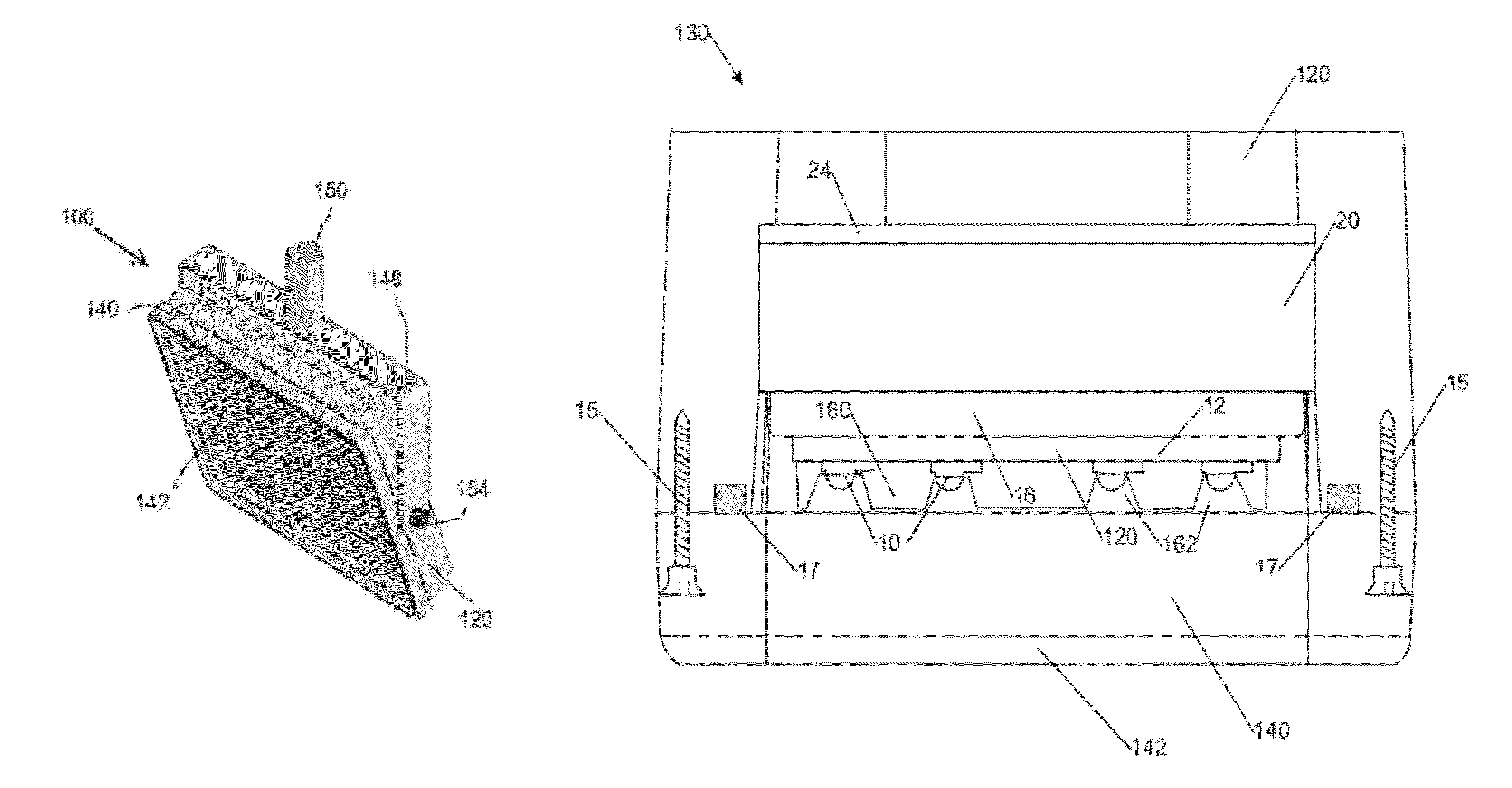
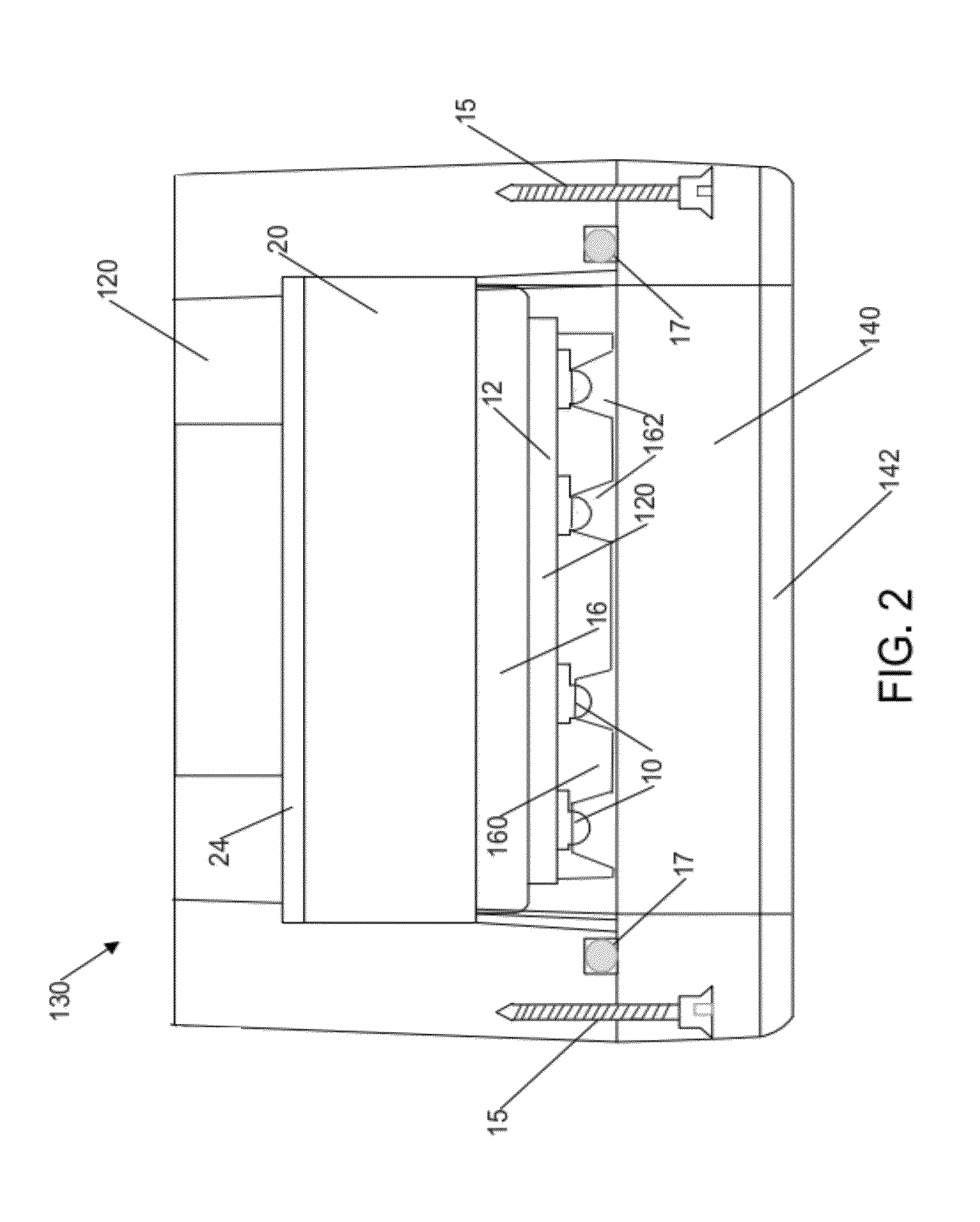
[0036]Heat sink 20, which abuts the back side of thermal bridge 16, conducts the heat transferred from the packaged LED through the PCB 12 and thermal bridge to the back shell 120 of housing 130. In the first embodiment shown in FIG. 4, the heat sink 20 may include a plurality of ribs 22 extending from its back side (the side opposite the front portion of the module). The spaces between the ribs 22, as well as any spaces between the ribs and the inner surface of the back shell 120, are filled with a high heat transfer potting compound 24. Such compounds are commercially-available from a number of sources, including Durapot™ 810, an alumina based, thermally conductive potting compound and adhesive available from Contronics Corp. (Brooklyn N.Y.).

second embodiment

[0037]In a second embodiment shown in FIG. 5, the heat sink 26 is formed as a solid block, without ribs. A high heat transfer potting compound 24 fills the space between a solid heat sink 24 and the inner surface of back shell 120.

[0038]A reflector array 160 with a plurality of conical or parabolic reflectors 162 is positioned over the front face of the PCB 12. The number of reflectors 162 and their spacing match that of the LED array so that when the reflector array and LED array are aligned, each LED 10 is centered within the bottom opening of its corresponding reflector to maximize the amount of light that is directed through the window.

[0039]The LED lighting system described above can be maintained at its safe operating temperature when the lamp is subjected to water temperatures of 50° C. or lower. When operated within its safe operating temperature, the inventive LED lighting system will achieve an average of 50,000 life hours. The integrated LED lamp provides an output illumi...


PUM


Abstract

A modular light unit for illuminating a hazardous underwater environment includes a housing having a front portion with a light transmissive window and a back shell portion which enclose a layered lighting assembly. The layered lighting assembly includes a PCB with an array of LEDs mounted thereon with the LEDs in thermal communication with a bottom surface of the PCB. A thermal bridge abuts the bottom surface of the PCB on one side and a heat sink on the other. A thermally conductive potting material fills spaces between the heat sink and the back shell portion. An underwater connector provides releasable connection to an electrical cable for providing power to drive the plurality of LEDs. A quick-release mechanical fastener is attached to the housing for releasably attaching the modular light unit to a support structure installed within the hazardous underwater environment.

Description

RELATED APPLICATIONS[0001]This application claims the priority of U.S. Provisional Application No. 61 / 228,159, filed Jul. 24, 2009, which is incorporated herein by reference.FIELD OF THE INVENTION[0002]The present invention relates to illumination systems and more particularly to illumination systems for hazardous underwater environments, including hazards such as nuclear radiation and / or contamination or in the ocean.BACKGROUND OF THE INVENTION[0003]A large number of reasons exist for lighting a large underwater environment including security, safety and illumination of work surfaces. Applications include oil drilling platforms, lighting around submarines and ships and for storage pools. In all applications it is desirable to use a high-efficiency, long-lifetime light source which can provide continuous lighting with minimal maintenance. Nowhere is the need for a low maintenance lighting system more pronounced than in nuclear refueling pools, spent fuel storage pools and in nuclear...

Claims


Application Information

Patent Timeline
Patent Type & Authority Patents(United States)
IPC IPC(8): F21V29/00F21V33/00G21C17/00
CPCF21V25/12F21V31/005F21S8/00F21V21/30F21Y2101/02F21Y2105/001F21W2131/411F21Y2105/10F21Y2115/10
Inventor POISSONNET, CYRILDE LA CRUZ, MARIOPETIT DE MANGE, EDWARD
Owner REMOTE OCEAN SYST
Why Eureka
Try Eureka