Service of the lighting systems in these areas takes excessive time, personnel may have
limited access, and their service results in
exposure of the maintenance personnel to
radiation.
Thus, maintenance personnel may be subjected to short periods of
radiation quite frequently for single
bulb changes or to extended periods of
exposure for “en
mass” changes, if it is even possible to
gain access to change the bulbs.
However, when the reactor is
shut down for a refueling outage, it is necessary to fill the entire refueling cavity with water, to limit the transmittal of
radiation as the fuel is being unloaded and loaded.
During this outage period, when maintenance is being performed on the reactor and when the fuel is being unloaded and loaded, it is costly and impractical to allocate maintenance personnel time for servicing the underwater lights.
Additionally, some lamps may be installed in isolated areas where
radiation flux can become quite high, such that access is available only for limited periods.
The nuclear maintenance workers who are responsible for these areas are required to wear cumbersome PPE (
Personal Protective Equipment) that makes high-dexterity repair work difficult or impossible.
As a result of this challenging situation, in practice many of these short-lifespan lights remain failed rather than being continually serviced, often resulting in some of these critical structures being poorly illuminated.
A number of underwater lights are the subjects of patents, however, for various reasons, these lights are not suitable for use in nuclear environments, either as fixed lights or as drop lights.
The housings are relatively large and cumbersome and not adjustable in direction once attached.
Such a construction would not be suitable for the wide angle illumination needed in a nuclear
pool or for the maneuverability required for a cable-suspended drop light.
The light is projected forward in a generally
narrow beam, resulting in the same limitations for use in nuclear applications as the lights of Olsson et al.
The flared shape of the housing places limitations on the maneuverability of such a device as a drop light.
Finally, and most importantly, none of the above-described lights make provisions for rapid changeout of burned-out or damaged bulbs.
Such changes are time-consuming and require multiple radiation exposures to effect a
bulb replacement.
If the entire lighting
assembly were to be replaced to avoid multiple exposures, such changes could become very expensive due to the complex construction of the assemblies.
Any facility which requires a large number of such light systems could find them to be prohibitively expensive to maintain
One drawback of HPS lighting is that its yellow-orange
color temperature (˜2,200 K) is not ideal for human vision, which is optimized for white (5,500 K) light.
While HPS lighting was the best option at the time the time of these patents, when using HPS lights in the underwater environment it can be difficult to discern objects and identify their true color due to the non-white color of the illumination.
An additional drawback is that HPS lamps can take several minutes before reaching full intensity, which delays the user's ability to see clearly within the underwater environment in an emergency situation, if these lights were not previously turned on.
However, complexities are introduced over traditional lighting sources by their need for drivers and
power factor correction.
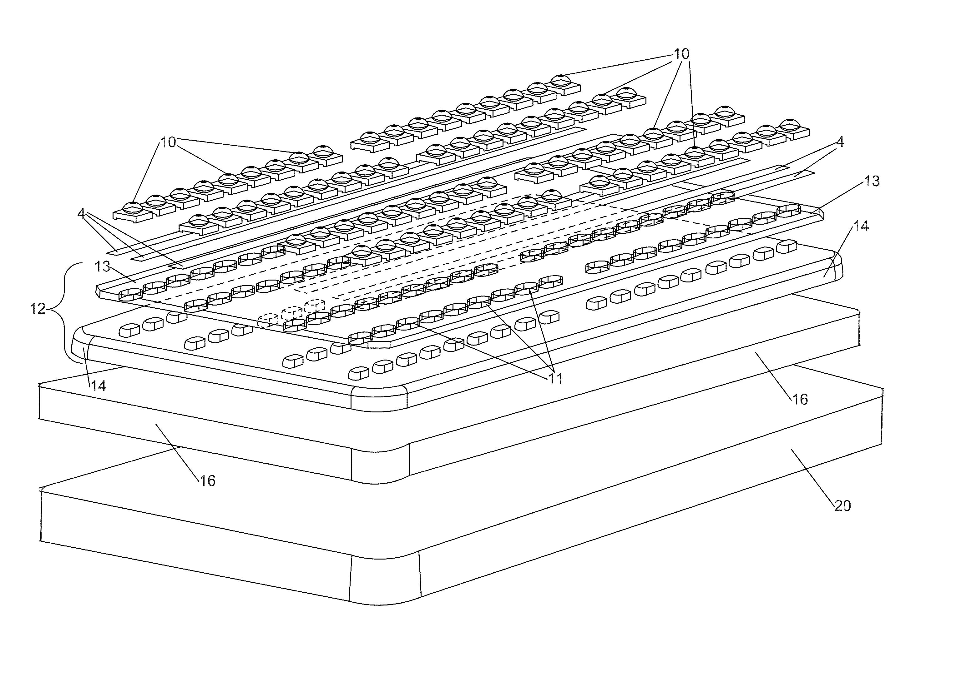
Despite these advantages, the major issue that has previously prevented the adoption of LED lighting is thermal management.
While typical LEDs can be operated at temperatures up to 185° C., that high of an
operating temperature is not conducive to long life and low maintenance.
Failure to address the heat dissipation needs of LED lighting will lead to severe degradation, which reduces operational lifetime, reduces visible light output, and negatively affects the color rendering.
While the disclosed
LED array solves many of the problems encountered with replacement of incandescent bulbs with LED arrays, it does not provide solutions for the special requirements of underwater operation, and particularly fails to address the problems involved in underwater operation in a hazardous environment such as a nuclear
spent fuel pool or
nuclear reactor.
Accordingly, obstacles remain to realization of LED-based lighting fixtures for use in hazardous underwater environments such as nuclear reactors and spent fuel pools.

