
Method and apparatus for establishing low frequency/ultra low frequency and very low frequency communications

a low frequency and ultra low frequency technology, applied in the direction of subaqueous/subterranean adaption, measurement using ac-dc conversion, instruments, etc., can solve the problems of complicated energy efficient transfer, inefficient conventional antennas, and inefficient antennas, so as to reduce eliminate the effect of ground return curren

Inactive Publication Date: 2012-10-30
BAE SYST INFORMATION & ELECTRONICS SYST INTERGRATION INC
View PDF12 Cites 99 Cited by
  • Summary
  • Abstract
  • Description
  • Claims
  • Application Information

AI Technical Summary

Benefits of technology

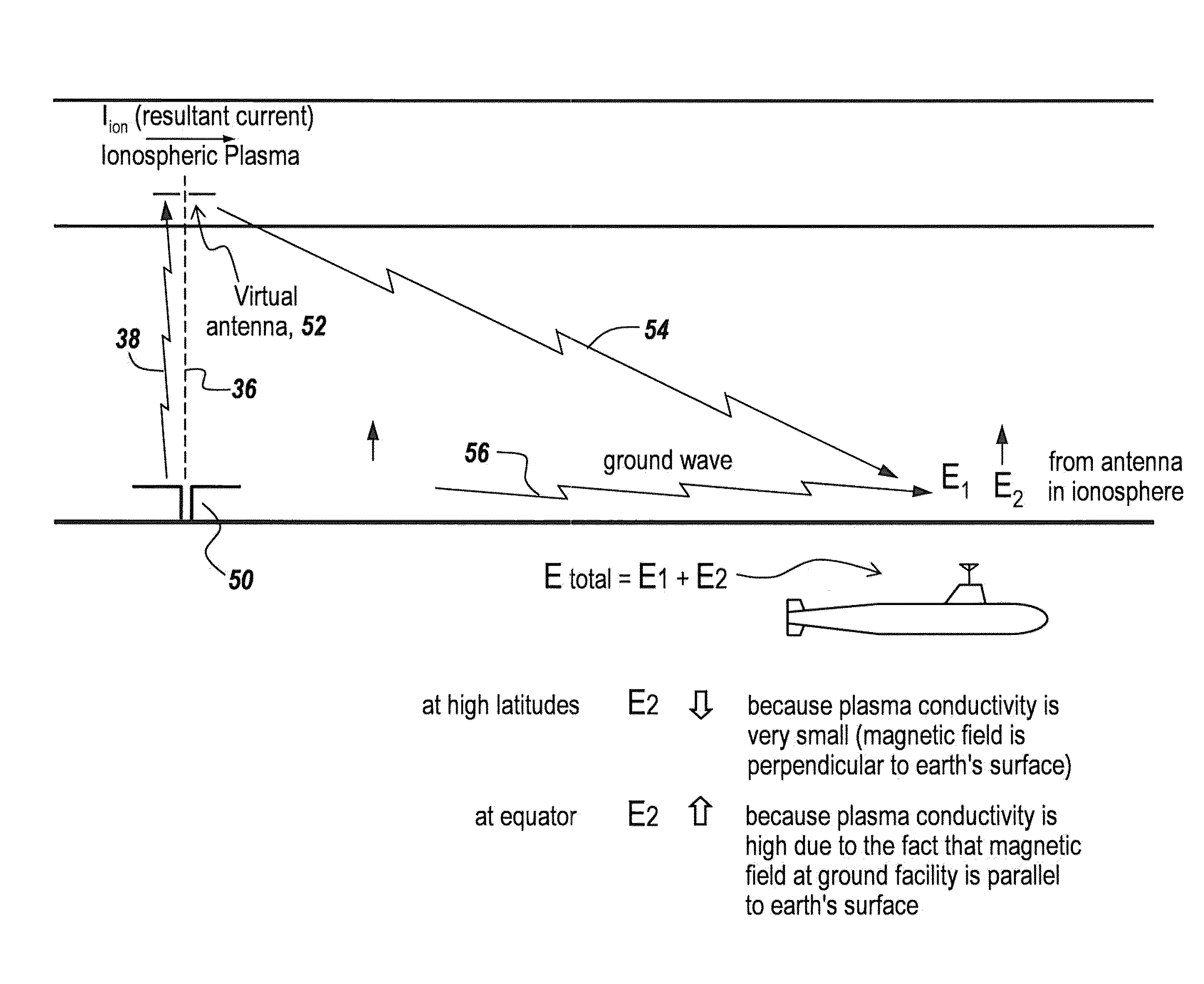
The patent text describes a method for improving low frequency communication and imaging by using a transmitting apparatus located at the magnetic equator and emitting pulsed radiation. This method results in a 25-30 dB improvement in signal strength compared to transmitting at high geomagnetic latitudes. The increased power at the magnetic equator is due to the fact that the magnetic field direction is parallel to the surface of the earth, and the conductance in the ionosphere is higher at the equator than at higher latitudes. The use of pulsed radiation also reduces the effect of ground return current and allows for robust communication. The patent text also mentions that this method can be used for submarines and subterranean object detection.

Problems solved by technology

There is a problem with ground antennas for ELF / ULF communication in that conventional antennas are very inefficient because while they project energy into free space, they also drive a return current of equal intensity inside the ground.
It is noted that the efficiency of an antenna is inversely proportional to the wavelength, and with these wavelengths the antenna is totally inefficient.
These shortened antennas further complicated the efficient transfer of energy to a subsurface vessel and because of the lack of signal strength it was common practice to order the submarines to the surface so that they could receive signals.
As mentioned before, the problem with low frequency signals is the effect of ground loop cancellation.
However, since electrojets generated by the solar wind are unreliable one was faced with having to solve the low frequency communications problem in another way.

Method used


Image

  • Method and apparatus for establishing low frequency/ultra low frequency and very low frequency communications
  • Method and apparatus for establishing low frequency/ultra low frequency and very low frequency communications
  • Method and apparatus for establishing low frequency/ultra low frequency and very low frequency communications

Examples


Embodiment Construction

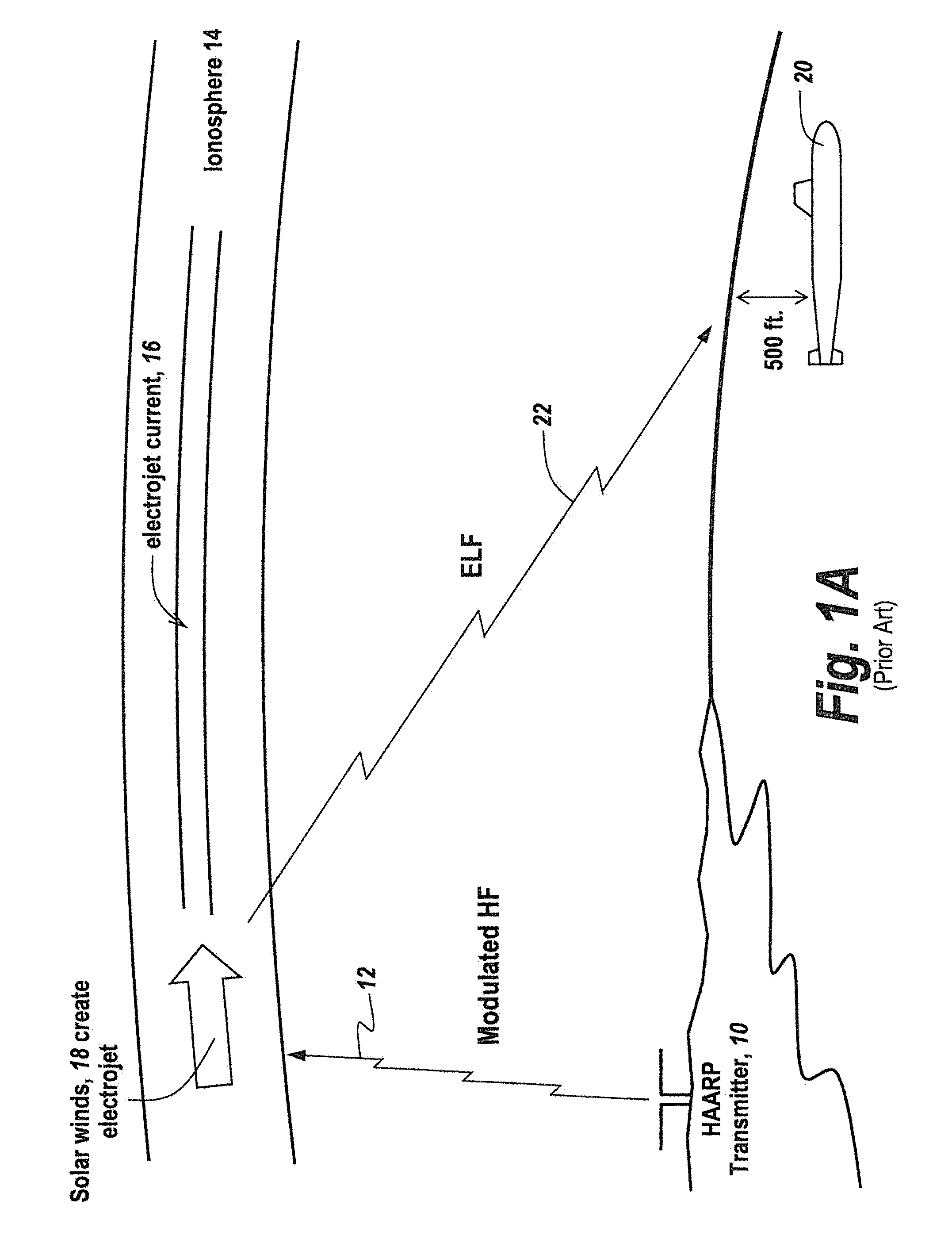
[0049]Referring now to FIG. 1, in the prior art and as described above, a HAARP transmitter 10 radiated an HF ELF-modulated signal 12 into the ionosphere 14 where it interacted with an electrojet current 16 that is created by solar winds 18.

[0050]When the HAARP transmitter is modulated with ELF modulation, an ELF signal is radiated from the virtual antenna provided by the electrojet current into the free space beneath the ionosphere where it is detected for instance by a submerged submarine 20 that may for instance be 500 feet below the surface of the ocean.

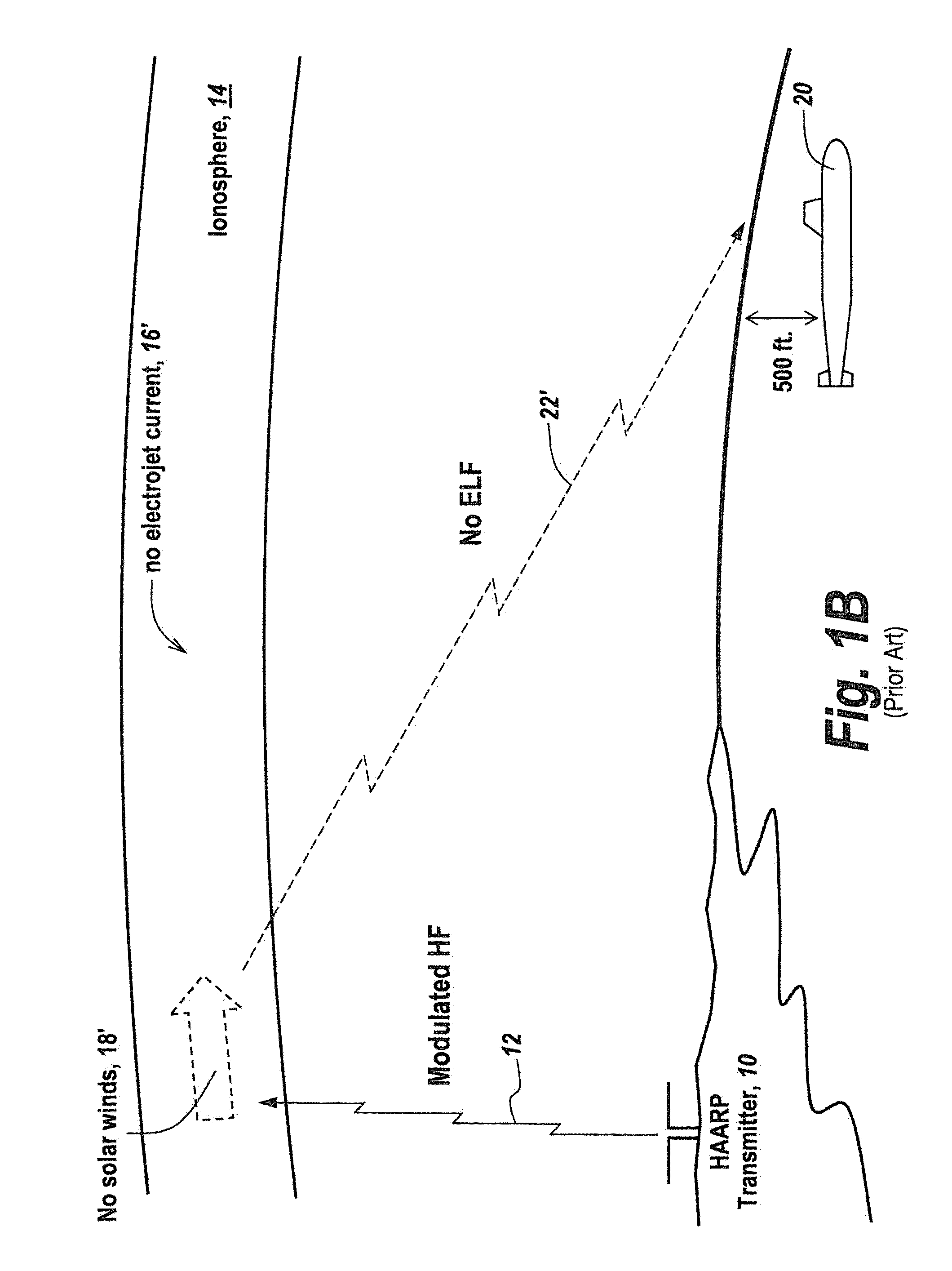
[0051]The problem with such a communications scheme is that, as illustrated at FIG. 1B, when there are no effective solar winds 18′ there is no electrojet current 16′ generated in ionosphere 14. This in turn means that there will be no ELF transmission as illustrated at 22′ and therefore no effective sub-sea communication.

[0052]Referring now to FIG. 2A, prior to the use of the HAARP technique, underwater communications were estab...


PUM


Abstract

A method for generating electromagnetic waves in the ELF / ULF comprising the steps of using a ground-based Horizontal Electric Dipole (HED) antenna to send electromagnetic pulses upwardly in the E-region of the ionosphere to form an oscillatory or pulsed electric field; allowing said pulsed electric field to interact with magnetized plasma of the lower ionosphere to generate a pulsed horizontal and vertical current which have associated Horizontal and Vertical Electric Dipole moment; and allowing them to radiate.

Description

RELATED APPLICATIONS[0001]This Application claims rights under 35 USC §119(e) from U.S. Application Ser. No. 61 / 138,746 filed Dec. 18, 2008, the contents of which are incorporated herein by reference.FIELD OF THE INVENTION[0002]This invention relates to the transmission of extremely low frequency signals and more particularly to a method and system for establishing reliable communications at these frequencies.BACKGROUND OF THE INVENTION[0003]For many years the ability to communicate at frequencies at for instance between 10 Hz and 1000 Hz has been important primarily for communication with submarines in which extremely low 10 Hz-2000 Hz signals are required to penetrate to the ocean depths or, for instance for finding underwater objects or doing underground exploration.[0004]There is a problem with ground antennas for ELF / ULF communication in that conventional antennas are very inefficient because while they project energy into free space, they also drive a return current of equal i...

Claims


Application Information

Patent Timeline
Patent Type & Authority Patents(United States)
IPC IPC(8): H04B13/02
CPCH01Q1/04H01Q9/16H01Q11/12
Inventor PAPADOPOULOS, KONSTANTINOS
Owner BAE SYST INFORMATION & ELECTRONICS SYST INTERGRATION INC
Learn More