Direct ultrashort laser system
a laser system and ultra-short technology, applied in laser details, instruments, optical devices, etc., can solve the problems of increasing the difficulty of measuring and correcting the spectral phase of the laser, affecting the accuracy of laser measurements, so as to eliminate undesired distortion, reduce the cost of implementation, and improve the accuracy of measurement
- Summary
- Abstract
- Description
- Claims
- Application Information
AI Technical Summary
Benefits of technology
Problems solved by technology
Method used
Image
Examples
first embodiment
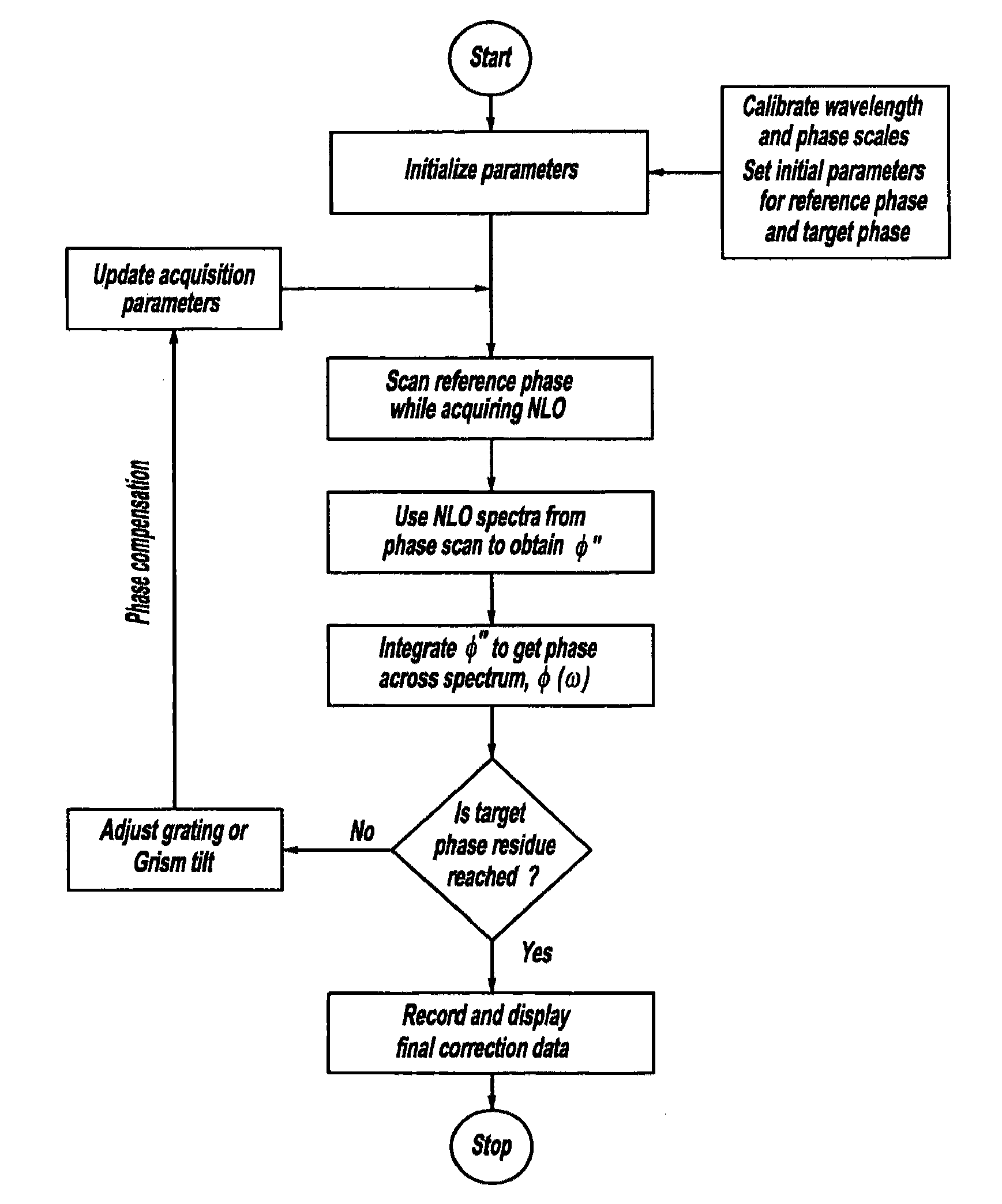
[0055]the present invention system, method, control system and software instructions is the simplest and readily usable with conventional laser devices but without requiring the expense of an adaptive pulse shaper. This embodiment allows for qualitative analysis by the programmed instructions in the computer control, and associated method, in order to measure and characterize phase distortions in a laser beam pulse and display them in a graphical manner. This allows the user to manually adjust the laser optics until the user is visually satisfied that the desired phase distortions have been reduced or eliminated. The method, controller and computer software act as follows by:
[0056]a. Introducing linear chirp, typically in the range of (−10,000 to +10,000 fs2). This value depends on the laser bandwidth and the estimated distortions; the smallest I imagined is +−1000 fs2 and the largest 100,000 fs2. Laser optics such as a pair of prisms, a pair of gratings, one grating with an associa...
third embodiment
[0083]A third embodiment variation of a nonadaptive deformable optic system 401 is shown in FIGS. 14 and 15. A thick substrate 403 and reflective layer 405 are preferably of the size and material types previously disclosed regarding FIGS. 11-13. A holder 407, however, has multiple threaded bores which receive manually adjustable, threaded screw actuators 409. Screw actuators 409 are spaced apart from each other and located adjacent the peripheral edge surrounding a reflective front which is openly accessible to a laser beam pulse. A ball bearing 411 or other pressure-bearing member is placed between a leading end of each screw actuator and the adjacent surface of the mirror. A compression or Belleville spring may optionally be disposed between a head of each screw actuator and the adjacent surface of the holder to maintain the adjusted positioning during use. Accordingly, each screw actuator can be individually adjusted in an incremental manner between multiple positions in order to...
fourth embodiment
[0084]FIGS. 16 and 17 illustrate a fourth embodiment variation of a nonadaptive deformable optic system 501. A thick glass substrate and reflective coating layer act as a phase front adjustable mirror 506 suitable to eliminate third order distortions. A holder 507 has flanges 508 which secure and maintain the position of a central portion of mirror 506. Multiple adjustable screw actuators 509 and bearing blocks 511 push against front and back side portions adjacent outboard corners of mirror 506, thereby causing deflection of the desired portions of the substrate and reflective layer. Yet another variation adheres a phase adjustable phase mirror, having a thickness T less than 1 mm, to a metal sheet which can also be bent by threaded screws. Moreover, it should be appreciated that any of these optic apparatus embodiments can be used with any of the laser system constructions and end uses disclosed hereinabove.
[0085]Another version of the present laser system is even simpler and less...
PUM
 Abstract
Description
Claims
Application Information
 - R&D
- Intellectual Property
- Life Sciences
- Materials
- Tech Scout
- Unparalleled Data Quality
- Higher Quality Content
- 60% Fewer Hallucinations
Browse by: Latest US Patents, China's latest patents, Technical Efficacy Thesaurus, Application Domain, Technology Topic, Popular Technical Reports.
© 2025 PatSnap. All rights reserved.Legal|Privacy policy|Modern Slavery Act Transparency Statement|Sitemap|About US| Contact US: help@patsnap.com


