

Apparatus for driving light emitting elements and electronic appliance employing the apparatus
a technology of light emitting elements and electronic appliances, applied in static indicating devices, instruments, display means, etc., can solve the problems limiting the maximum current the constant-current driver can control, so as to achieve the effect of increasing the temperature of the constant-current driver and deteriorating the efficiency of the apparatus
- Summary
- Abstract
- Description
- Claims
- Application Information
AI Technical Summary
Benefits of technology
Problems solved by technology
Method used
Image

Examples
first embodiment
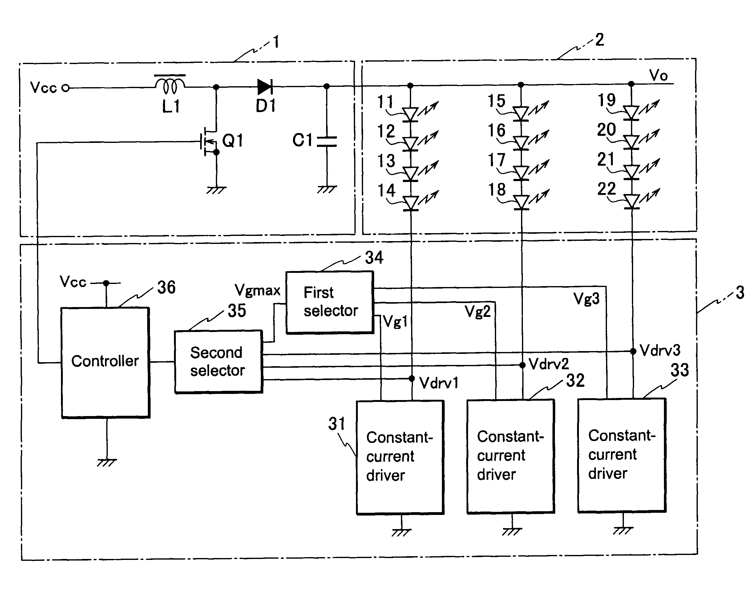
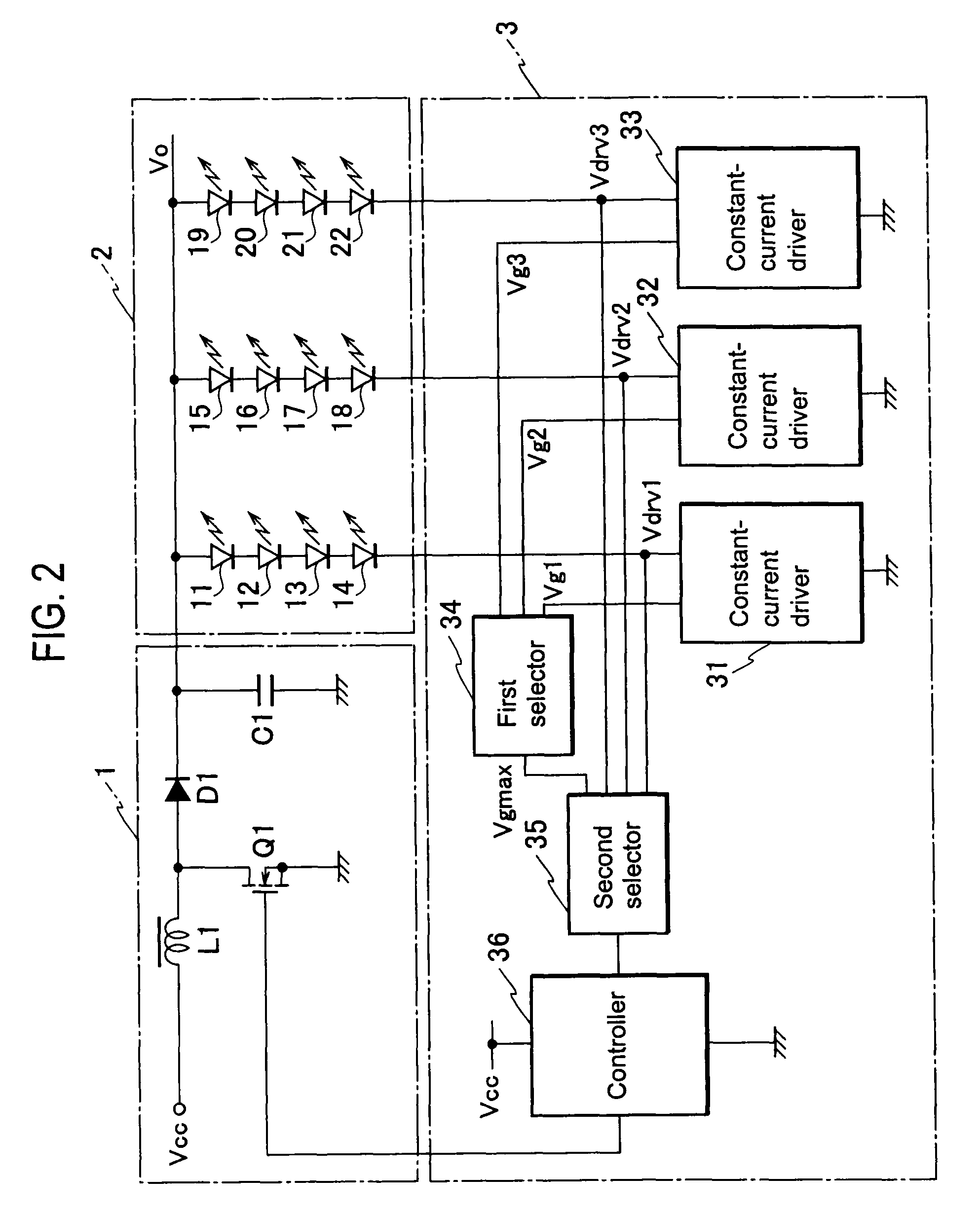
[0027]FIG. 2 is a circuit diagram illustrating an apparatus for driving light emitting elements according to the first embodiment of the present invention. In FIG. 2, the apparatus includes a power source circuit 1, a light emitting element section 2, and a light emitting element drive section 3.
[0028]The power source circuit 1 includes a first series circuit and a rectify-smooth circuit. The first series circuit is connected between an input power source Vcc and the ground and includes a step-up reactor L1 and a switching element Q1 such as a MOSFET. The rectify-smooth circuit is connected in parallel with the switching element Q1 between the drain and source thereof and includes a rectifying diode D1 and a smoothing capacitor C1.
[0029]The light emitting element section 2 includes three arrays of light emitting elements, i.e., an array of series-connected four light emitting elements 11 to 14, an array of series-connected four light emitting elements 15 to 18, and an array of serie...
second embodiment
[0061]FIG. 8 is a circuit diagram illustrating an apparatus for driving light emitting elements according to the second embodiment of the present invention. A power source circuit of the apparatus according to the second embodiment has a first series circuit that is connected between an input power source Vcc and the ground and contains a step-up reactor L1 and a switching element Q1 such as a MOSFET. The power source circuit also has a rectify-smooth circuit that is connected between and in parallel with the drain and source of the switching element Q1 and includes a rectifying diode D1 and a smoothing capacitor C1.
[0062]An array of series connected three light emitting elements 11 to 13 has a first end connected to a first end of the smoothing capacitor C1. Between a second end of the array of light emitting elements and the ground, there is connected a series circuit including a MOSFET Q30 and a resistor R1. The MOSFET Q30, the resistor R1, an operational amplifier 40, and a refe...
first modification
[0068]FIG. 9 is a circuit diagram illustrating a power source circuit according to a first modification of the present invention. The power source circuit la shown in FIG. 9 is of a charge pump type and can substitute for the power source circuit 1 of any one of the first and second embodiments. The power source circuit la includes a series circuit that is connected between a power source Vcc and the ground and consists of a diode D2, a capacitor C2, and an n-type MOSFET serving as a switching element Q3.
[0069]Ends of a series circuit of the capacitor C2 and switching element Q3 are connected to a series circuit of a diode D1 and a smoothing capacitor C1. Between a connection point of the capacitor C2 and switching element Q3 and the ground, there is connected a series circuit of a p-type MOSFET serving as a switching element Q2 and a power source Vreg2. A driver 37 alternately turns on / off the switching elements Q2 and Q3. The driver 37 corresponds to the controller 36 shown in FIG...
PUM
 Abstract
Description
Claims
Application Information