Cyclo olefin polymer and copolymer medical devices

a technology of cyclo olefin and medical devices, applied in the field of in vivo surgical field illumination, can solve the problems of unstable transmission characteristics, heat and weight penalty of light sources, and limited use of body cavities for diagnosis and or therapy

Active Publication Date: 2012-11-27
INVUITY
View PDF15 Cites 77 Cited by
  • Summary
  • Abstract
  • Description
  • Claims
  • Application Information

AI Technical Summary

Benefits of technology

[0003]The devices described below provide for surgical retraction or illumination, or both, with devices made primarily of an amorphous polyolefin, cyclo olyfin polymer. Preferably, a retractor formed primarily of cycle olelfin polymer is used as the illumination device. A surgical illumination system formed of cyclo olefin polymer (C.O.P.) may include a generally cylindrical light waveguide having a bore sized to accommodate one or more surgical instruments, an illumination source, an illumination conduit for conducting illumination energy from the illumination source, and an adapter ring for engaging the illumination conduit and coupling illumination energy from the illumination conduit to the light waveguide. The adapter ring may permit relative movement between the illumination conduit and the light waveguide.
[0007]A C.O.P. blade insert illumination system includes one or more illumination elements composed of cyclo olefin polymer. The C.O.P. illumination elements operate as a waveguide and may incorporate optical components such as, for example, symmetric or asymmetric facets, lenses, gratings, prisms and or diffusers to operate as precision optics for customized delivery of the light energy. The illumination elements may be modular, allowing components to be mixed and matched for different sizes of blade retractors, or may be a single integrated unit. Each module may also have different performance characteristics such as a diffuse light output or a focused light output allowing users to mix and match optical performance as well.

Problems solved by technology

Illumination of body cavities for diagnosis and or therapy has been limited by overhead illumination.
High intensity incandescent lighting has been developed and has received limited acceptance as well as semiconductor and laser lighting, however these light sources have a heat and weight penalty associated with their use.
Conventional waveguide materials that are suggested for medical use suffer from unstable transmission characteristics under extended use and their transmission characteristics also change when sterilized using conventional techniques.
Additionally, precision optical polymers have limited mechanical properties which limits their application in medical / surgical situations.

Method used


Image

  • Cyclo olefin polymer and copolymer medical devices
  • Cyclo olefin polymer and copolymer medical devices
  • Cyclo olefin polymer and copolymer medical devices

Examples


Embodiment Construction

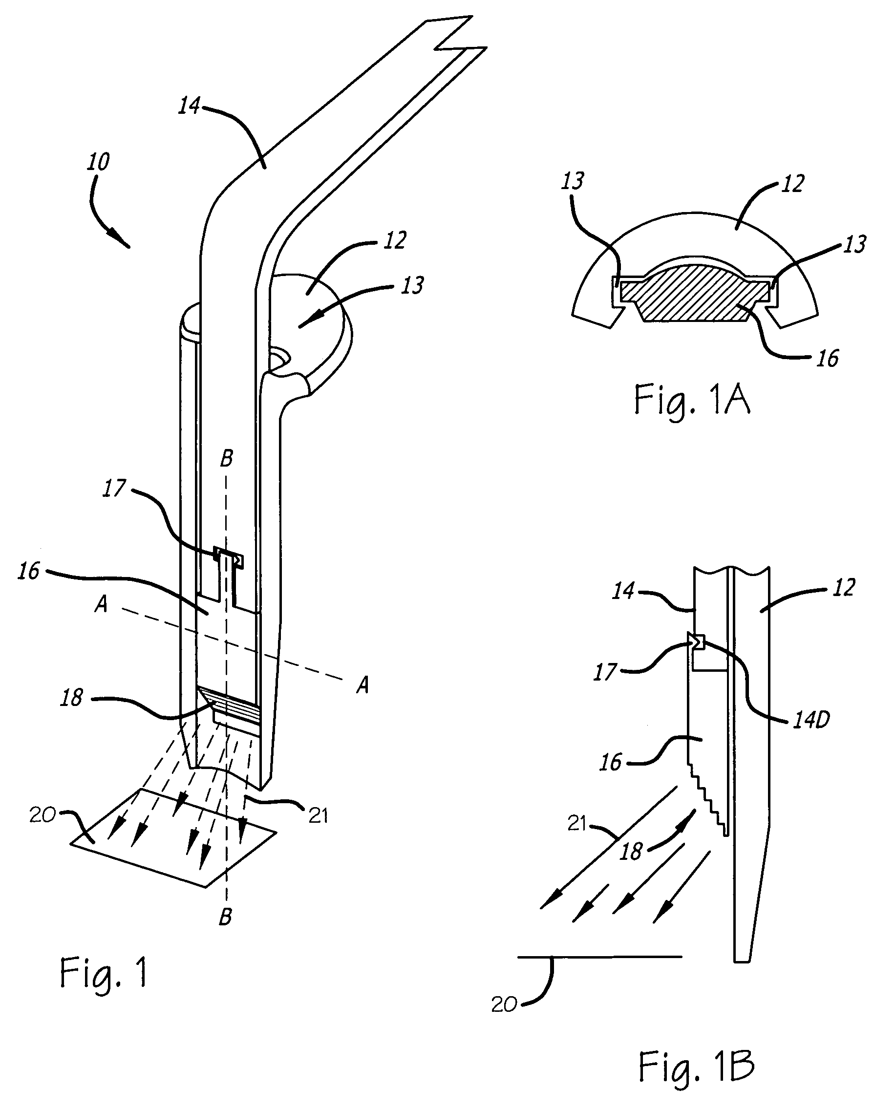
[0070]Retractor illumination system 10 of FIG. 1 includes blade retractor 12 including channel 13 to engage a fiber optic input 14 and waveguide illuminator 16. Latch 17 serves to mechanically attach waveguide illuminator 16 to fiber optic input 14 so that the resulting assembly may be moved up and down in channel 13 to any position suitable for illumination. The optical coupling between fiber input 14 and waveguide illuminator 16 is a simple face-to-face coupling, which may be enhanced by use of an index matching gel, or other similar material, applied to either the fiber input 14 or the waveguide illuminator 16 or both. Light entering waveguide illuminator 16 is contained within the waveguide with minimal light loss until it reaches output optical structures such as output structures 18, where light exits to illuminate the predetermined illumination area 20. Output optical structures 18 may include one or more stair stepped facets or lenses that may include a radius or angled face...


PUM

PropertyMeasurementUnit
diameteraaaaaaaaaa
diameteraaaaaaaaaa
diameteraaaaaaaaaa

Abstract

Medical retractors including light guides made of cyclo olefin polymer.

Description

FIELD OF THE INVENTIONS[0001]The inventions described below relate to the field of in vivo surgical field illumination during surgical procedures.BACKGROUND OF THE INVENTIONS[0002]Illumination of body cavities for diagnosis and or therapy has been limited by overhead illumination. High intensity incandescent lighting has been developed and has received limited acceptance as well as semiconductor and laser lighting, however these light sources have a heat and weight penalty associated with their use. Conventional light sources rely on fiber optic and similar waveguide materials to conduct light to a body cavity. Conventional waveguide materials that are suggested for medical use suffer from unstable transmission characteristics under extended use and their transmission characteristics also change when sterilized using conventional techniques. Additionally, precision optical polymers have limited mechanical properties which limits their application in medical / surgical situations.SUMMA...

Claims


Application Information

Patent Timeline
Patent Type & Authority Patents(United States)
IPC IPC(8): A61B1/32A61B1/267
CPCA61B1/267A61B17/02A61B17/0206A61B17/3421A61B19/5202A61B1/06A61L29/041A61B1/0669C08L23/00A61B2019/5206A61B90/30A61B2090/306A61B90/35A61B1/0625
Inventor GREY, THOMAS L.ERISMANN, FERNANDOVAYSER, ALEX
Owner INVUITY
Why Eureka
Try Eureka