Catalyst containing oxygen transport membrane

a technology of oxygen transport membrane and catalyst, which is applied in the direction of diaphragms, specific gas purification/separation, inorganic chemistry, etc., can solve the problems of affecting material elasticity, and material fragility, and reducing the effect of oxygen transport membran

Active Publication Date: 2012-12-04
PRAXAIR TECH INC
View PDF21 Cites 27 Cited by
  • Summary
  • Abstract
  • Description
  • Claims
  • Application Information

AI Technical Summary

Benefits of technology

[0016]The porous support layer can have a permeability of between 0.25 Darcy and about 0.5 Darcy and an average porosity of greater than about 20 percent. The porous support layer can be formed by freeze casting. The solution can be an aqueous metal ion solution containing 20 mol % Gd(NO3)3 and 80 mol % Ce(NO3)3 that when sintered forms Gd0.8Ce0.2O2-δ. A pressure can be established on the side of the support layer to assist in the infiltration of the solution or the pores can first be evacuated of air using a vacuum to further assist in wicking of the solution and prevent the opportunity of trapped air in the pores preventing wicking of the solution all the way through the support structure to the intermediate layer. The composite oxygen transport membrane can be heated in service or alternatively, can be heated prior to being placed in service. The term “service” as used herein and in the claims means contacting the composite oxygen transport membrane with an oxygen containing substance and a combustible substance and oxidizing the combustible substance with oxygen transported through the membrane to generate the heat.

Problems solved by technology

Another limiting factor to the performance of an oxygen transport membrane concerns the supporting layers that, although can be active, that is oxygen ion or electron conducting, the layers themselves can consist of a network of interconnected pores that can limit diffusion of the oxygen or fuel or other substance through the membrane to react with the oxygen.
The high porosity, however, tends to weaken such a structure.
While perovskite materials will exhibit a high oxygen flux, such materials tend to be very fragile under operational conditions such as in the heating of a fluid.
The end result is that at the fuel side, the material will tend to expand relative to the air side and a dense layer will therefore, tend to fracture.
However, the problem with the use of a fluorite, such as a stabilized zirconia, is that such a material has a lower oxygen ion conductivity.

Method used


Image

  • Catalyst containing oxygen transport membrane
  • Catalyst containing oxygen transport membrane
  • Catalyst containing oxygen transport membrane

Examples


Embodiment Construction

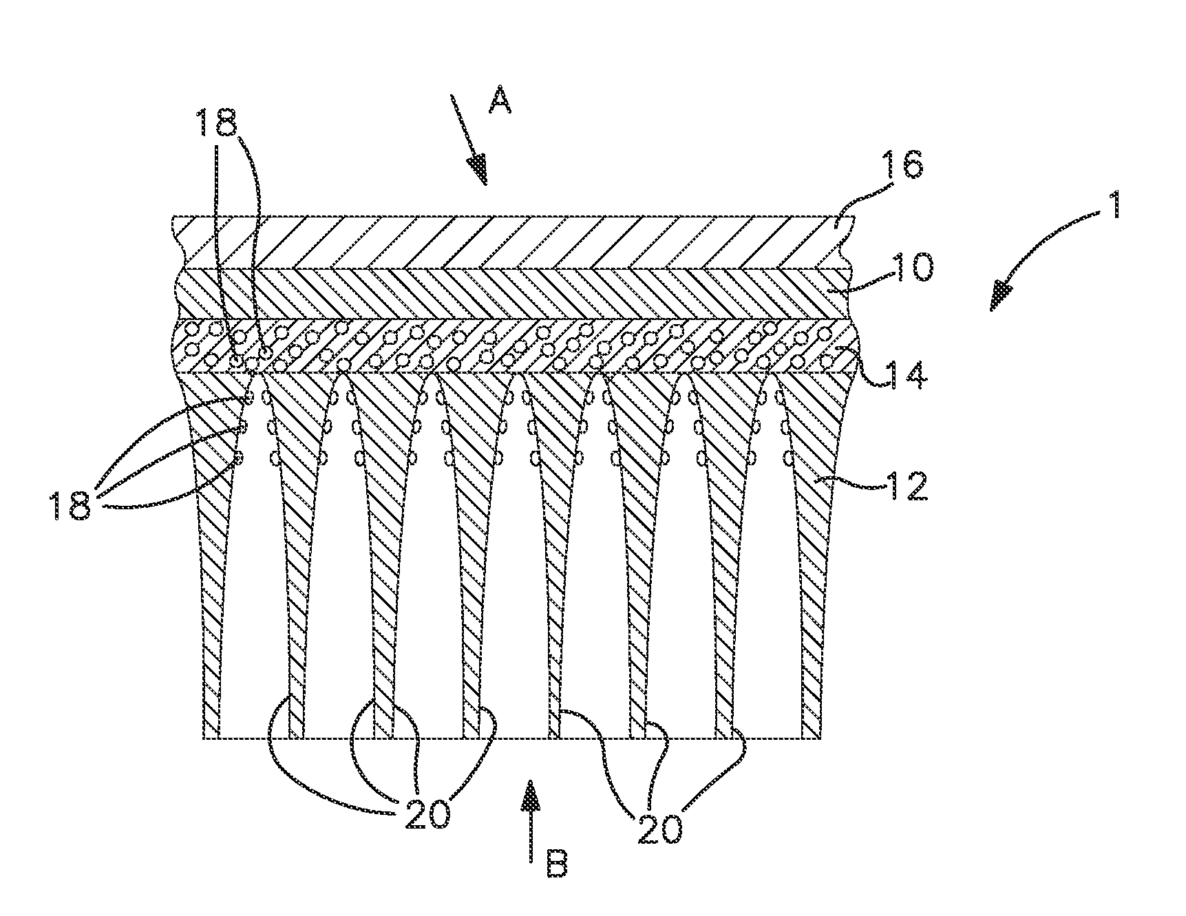
[0021]With reference to FIG. 1, a sectional view of a composite oxygen transport membrane element 1 in accordance with the present invention is illustrated. As could be appreciated by those skilled in the art, such composite oxygen transport membrane element 1 could be in the form of a tube or a flat plate. Such composite oxygen transport membrane element 1 would be one of a series of such elements situated within a device to heat a fluid such as a boiler or other reactor having such a requirement.

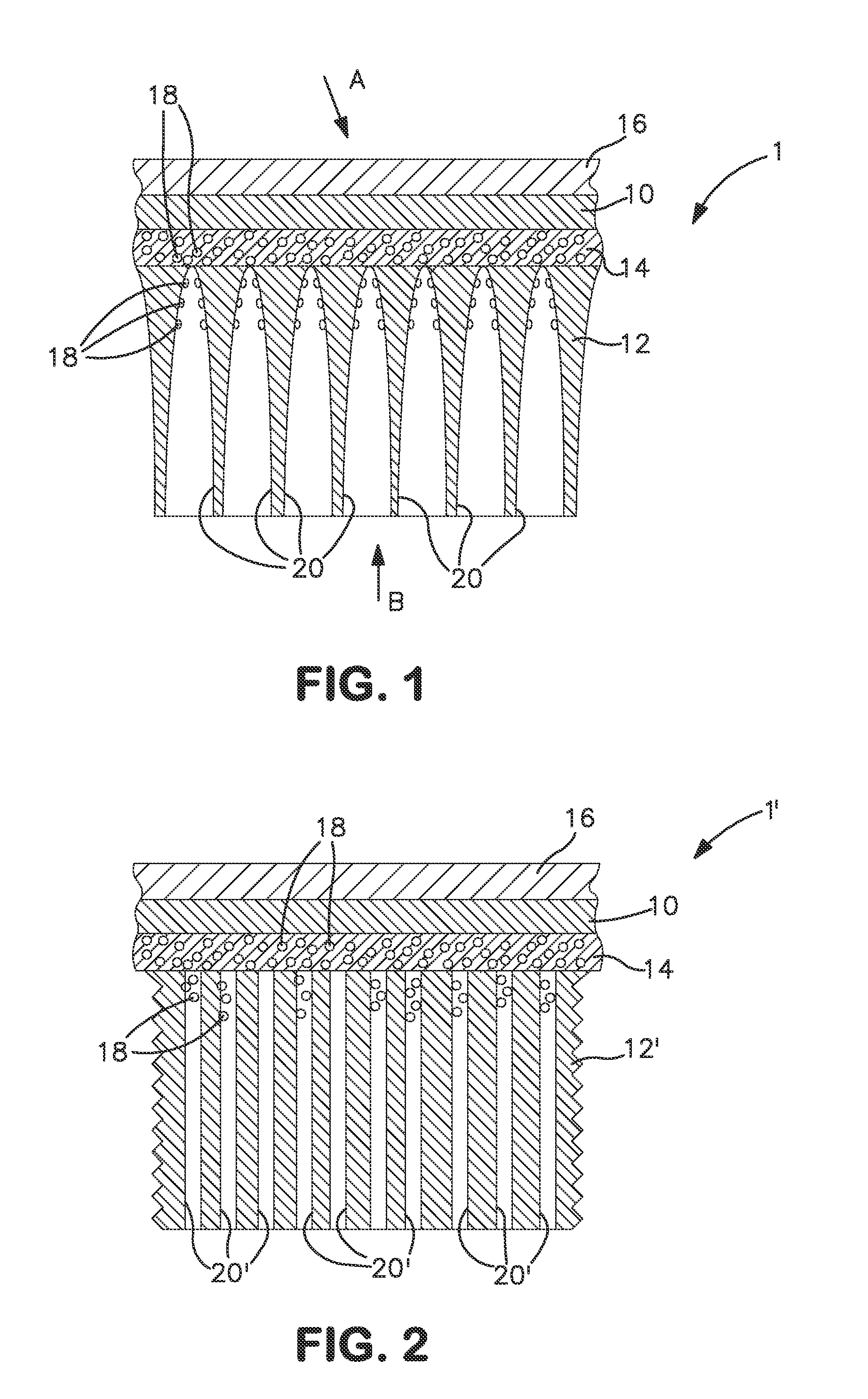
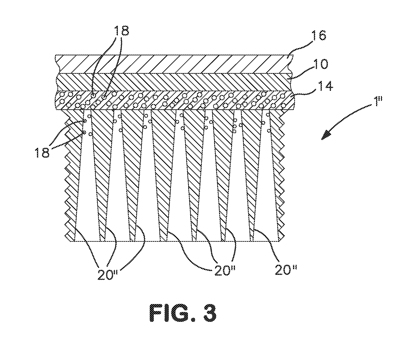
[0022]Composite oxygen transport membrane element 1 is provided with a dense layer 10, a porous support layer 12 and an intermediate porous layer 14 located between the dense layer 10 and the porous support layer 12. A preferable option is, as illustrated, to also include a porous surface exchange layer 16 in contact with the dense layer 10, opposite to the intermediate porous layer 14. Catalyst particles 18 are located in the intermediate porous layer 14 that are formed of a catalyst sele...


PUM

PropertyMeasurementUnit
porosityaaaaaaaaaa
pore diameteraaaaaaaaaa

Abstract

A composite oxygen transport membrane having a dense layer, a porous support layer and an intermediate porous layer located between the dense layer and the porous support layer. Both the dense layer and the intermediate porous layer are formed from an ionic conductive material to conduct oxygen ions and an electrically conductive material to conduct electrons. The porous support layer has a high permeability, high porosity, and a high average pore diameter and the intermediate porous layer has a lower permeability and lower pore diameter than the porous support layer. Catalyst particles selected to promote oxidation of a combustible substance are located in the intermediate porous layer and in the porous support adjacent to the intermediate porous layer. The catalyst particles can be formed by wicking a solution of catalyst precursors through the porous support toward the intermediate porous layer.

Description

RELATED APPLICATIONS[0001]The present application claims priority from U.S. Application Ser. No. 61 / 291,221, filed Jan. 22, 2010, which is incorporated by reference herein in its entirety.U.S. GOVERNMENT RIGHTS[0002]This invention was made with Government support under. Cooperative-Agreement No. DE-FC26-07NT43088, awarded by the United States Department of Energy. The Government has certain rights in this invention.FIELD OF THE INVENTION[0003]The present invention relates to a composite oxygen transport membrane in which catalyst particles, selected to promote oxidation of a combustible substance, are located within an intermediate porous layer that is in turn located between a dense layer and a porous support layer and within the porous support and a method of applying the catalyst to the intermediate porous layer and the porous support layer through wicking of catalyst precursors through the porous support layer to the intermediate porous layer.BACKGROUND OF THE INVENTION[0004]Oxy...

Claims


Application Information

Patent Timeline
Patent Type & Authority Patents(United States)
IPC IPC(8): C25B13/04H01M8/10B01D53/22C25C7/04H01M8/12
CPCB01D53/228B01D69/12B01D71/024C01B13/0255B01D2325/021B01D2325/10C01B2210/0046
Inventor CHRISTIE, GERVASE MAXWELLWILSON, JAMIE ROBYNVAN HASSEL, BART ANTONIE
Owner PRAXAIR TECH INC
Why Eureka
Try Eureka