
Exhaust device for a diesel engine

a technology for exhaust gas and diesel engines, which is applied in the direction of lighting and heating apparatus, separation processes, instruments, etc., can solve the problems of insufficient igniting means and burnt flammable gas, and achieve the effects of enhancing the temperature of the exhaust gas, preventing and reducing the heat-damaging of the oxidation catalys

Inactive Publication Date: 2012-12-25
KUBOTA CORP
View PDF25 Cites 13 Cited by
  • Summary
  • Abstract
  • Description
  • Claims
  • Application Information

AI Technical Summary

Benefits of technology

The present invention is an exhaust device for a diesel engine that can ensure the combustion of flammable gas and prevent the heat-damaging of the oxidation catalyst. The exhaust device includes a liquid-fuel supply source, a gas generator, a flammable-gas pipe, and an oxidation catalyst. The flammable gas is burnt with the oxidation catalyst to produce combustion heat that heats the exhaust gas. This ensures the combustion of the flammable gas even with a small amount of oxygen present in the exhaust gas. The invention also prevents the formation of high-temperature combustion portions in the oxidation catalyst that could damage it. The exhaust gas is heated by the combustion heat from the oxidation catalyst and mixed with the flammable gas, which is burnt to produce more combustion heat and ensure the combustion of the flammable gas.

Problems solved by technology

However, in the conventional exhaust device for a diesel engine, the flammable gas is burnt only with the oxygen contained in the exhaust gas, and besides no igniting means is provided.
Therefore, it causes problems.

Method used


Image

  • Exhaust device for a diesel engine
  • Exhaust device for a diesel engine
  • Exhaust device for a diesel engine

Examples


Embodiment Construction

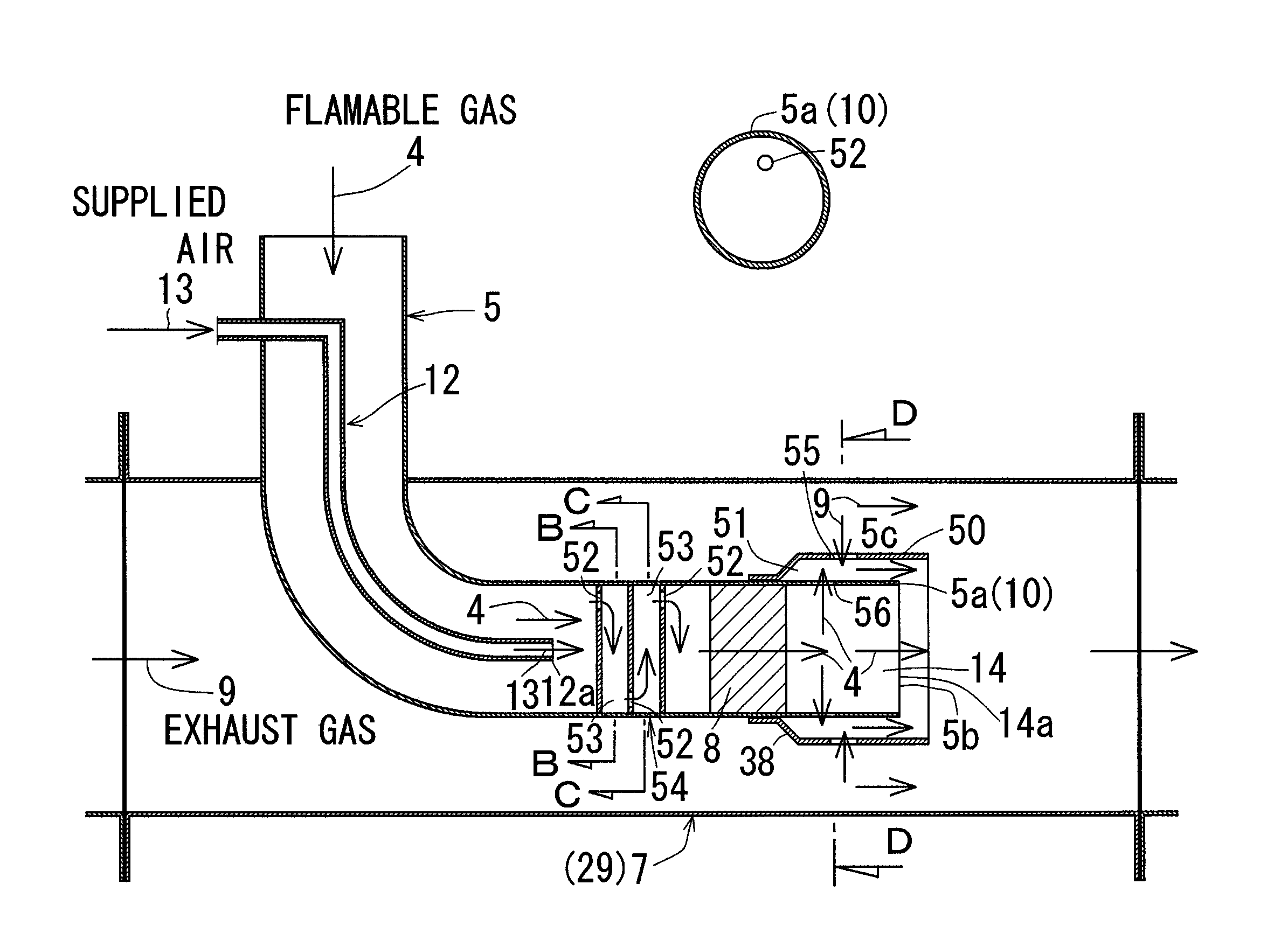
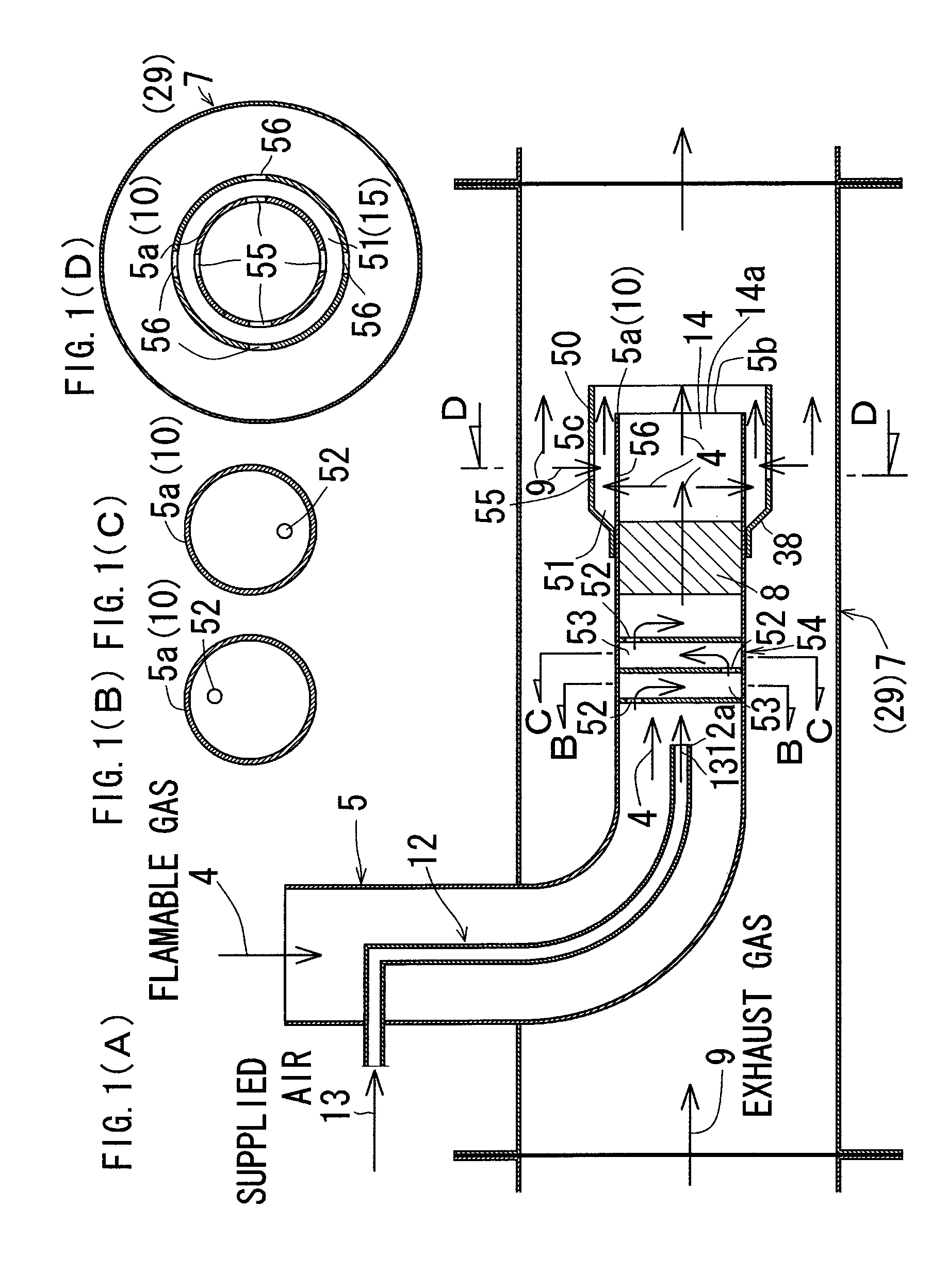
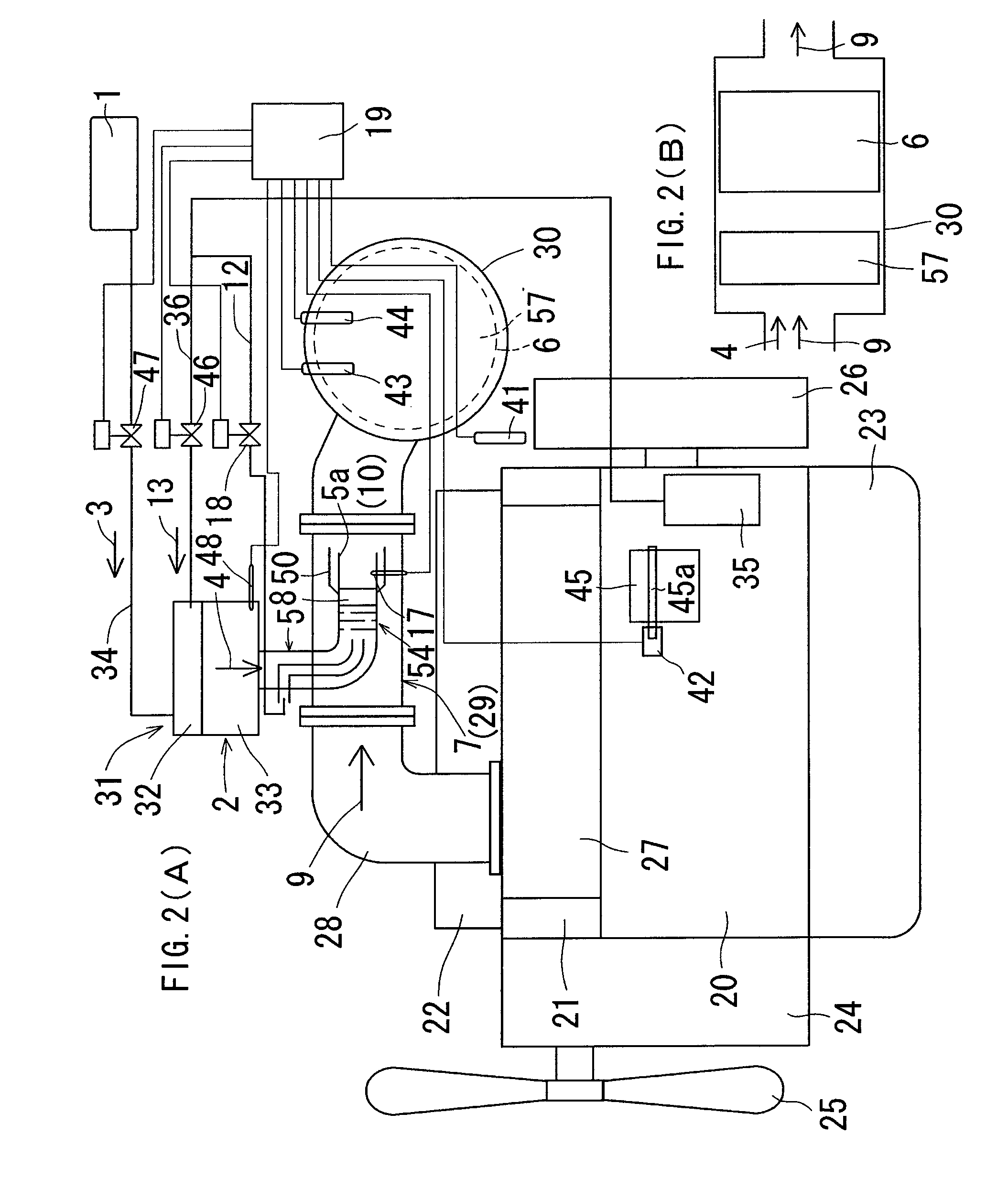
[0061]Embodiments of the present invention are explained based on the attached drawings. FIGS. 1 and 2 show an exhaust device for a diesel engine according to a first embodiment of the present invention. FIG. 3 shows a second embodiment according to the present invention. In each of these embodiments, an explanation is given to an exhaust device for a multi-cylinder vertical diesel engine.

[0062]The first embodiment of the present invention is outlined as follows.

[0063]This engine, as shown in FIG. 2, comprises a cylinder block 20 onto which a cylinder head 21 is assembled, a head cover 22 being assembled to an upper portion of the cylinder head 21 and an oil pan 23 being assembled to a lower portion of the cylinder block 20, the cylinder block 20 having a front portion to which a gear case 24 is assembled, an engine-cooling fan 25 being arranged at a front portion of the gear case 24, a fly-wheel 26 being disposed at a rear portion of the cylinder block 20. The cylinder head 21 has ...


PUM

PropertyMeasurementUnit
flammableaaaaaaaaaa
areaaaaaaaaaaa
temperatureaaaaaaaaaa

Abstract

A flammable-gas led-out pipe (5) has a terminal end portion (5a) disposed in an exhaust-gas route (7) and a metal cylinder (10) is arranged at the terminal end portion (5a) of the flammable-gas led-out pipe (5). An oxidation catalyst (8) is disposed within the metal cylinder (10). On an upstream side of the oxidation catalyst (8), an air-supply passage (12) is opened to provide an outlet (12a) and the flammable gas (4) merges with supplied air (13). The flammable gas (4) is burnt with the oxidation catalyst (8) to produce catalyst-combustion heat, which is radiated from an outer peripheral surface of the metal cylinder (10) into the exhaust gas (9) in the exhaust-gas route (7) and the exhaust gas (9) heated by this heat-radiation is mixed with the flammable gas (4) that has passed through the oxidation catalyst (8).

Description

TECHNICAL FIELD[0001]The present invention concerns an exhaust device for a diesel engine and more specifically relates to an exhaust device for a diesel engine able to ensure the combustion of flammable gas and to inhibit the damage of an oxidation catalyst caused by heat.BACKGROUND ART[0002]An example of the conventional exhaust devices for a diesel engine comprises a liquid-fuel supply source which supplies liquid fuel to a gas generator, which converts the liquid fuel to flammable gas as well as the present invention. A flammable-gas pipe led out of the gas generator is communicated with an exhaust-gas route on an upstream side of a diesel-particulate-filter. An oxidation catalyst is arranged upstream of this filter in the exhaust-gas route and the flammable gas is burnt with the oxidation catalyst to produce combustion heat that heats the exhaust gas. The thus heated exhaust gas burns the exhaust-gas fine particles remaining at the filter.[0003]However, in the conventional exha...

Claims


Application Information

Patent Timeline
Patent Type & Authority Patents(United States)
IPC IPC(8): B01D53/34F01N3/025F01N3/035
CPCF01N3/025F01N3/035F01N3/106F01N13/0097F01N2240/30F01N2470/24F01N2560/06F01N2240/14B01D53/86F01N3/08F01N3/28
Inventor NAKAHIRA, TOSHIO
Owner KUBOTA CORP
Learn More