Charged particle beam detection unit with multi type detection subunits

a detection unit and charge-charged particle technology, applied in the field of multi-detectors, can solve the problems of less able to detect defects, less performance of optical inspection tools such as optical systems, and the throughput of optical systems is much lower than that of current optical inspection systems, so as to reduce the intensity of received light

Active Publication Date: 2013-01-08
ASML NETHERLANDS BV
View PDF4 Cites 7 Cited by
  • Summary
  • Abstract
  • Description
  • Claims
  • Application Information

AI Technical Summary

Problems solved by technology

Shrinking of the design nodes to 22 nm or even smaller, however, makes the defect inspection tool, such as an optical system, less able to detect the defects, owing to the optical resolution of light sources used being equal to or larger than the defect dimension.
Further, in a VC (voltage contrast) mode of inspection the e-beam inspection tool can inspect for under-layer defects, the performance of which is almost impossible for current-day optical inspection systems to match.
Nevertheless, due to restrictions of the e-beam system per se, throughput thereof is much lower than that of optical systems.
Up to the present day, there still is no single e-beam system that can handle both large current and small current inspections.

Method used


Image

  • Charged particle beam detection unit with multi type detection subunits
  • Charged particle beam detection unit with multi type detection subunits
  • Charged particle beam detection unit with multi type detection subunits

Examples


Embodiment Construction

[0016]Reference will now be made in detail to specific embodiments of the invention. Examples of these embodiments are illustrated in the accompanying drawings. While the invention will be described in conjunction with these specific embodiments, it will be understood that it is not intended to limit the invention to these embodiments. On the contrary, it is intended to cover alternatives, modifications, and equivalents as may be included within the spirit and scope of the invention as defined by the appended claims. In the following description, numerous specific details are set forth in order to provide a thorough understanding of the present invention. The present invention may be practiced without some or all of these specific details. In other instances, well known process operations are not described in detail in order not to obscure unnecessarily the present invention.

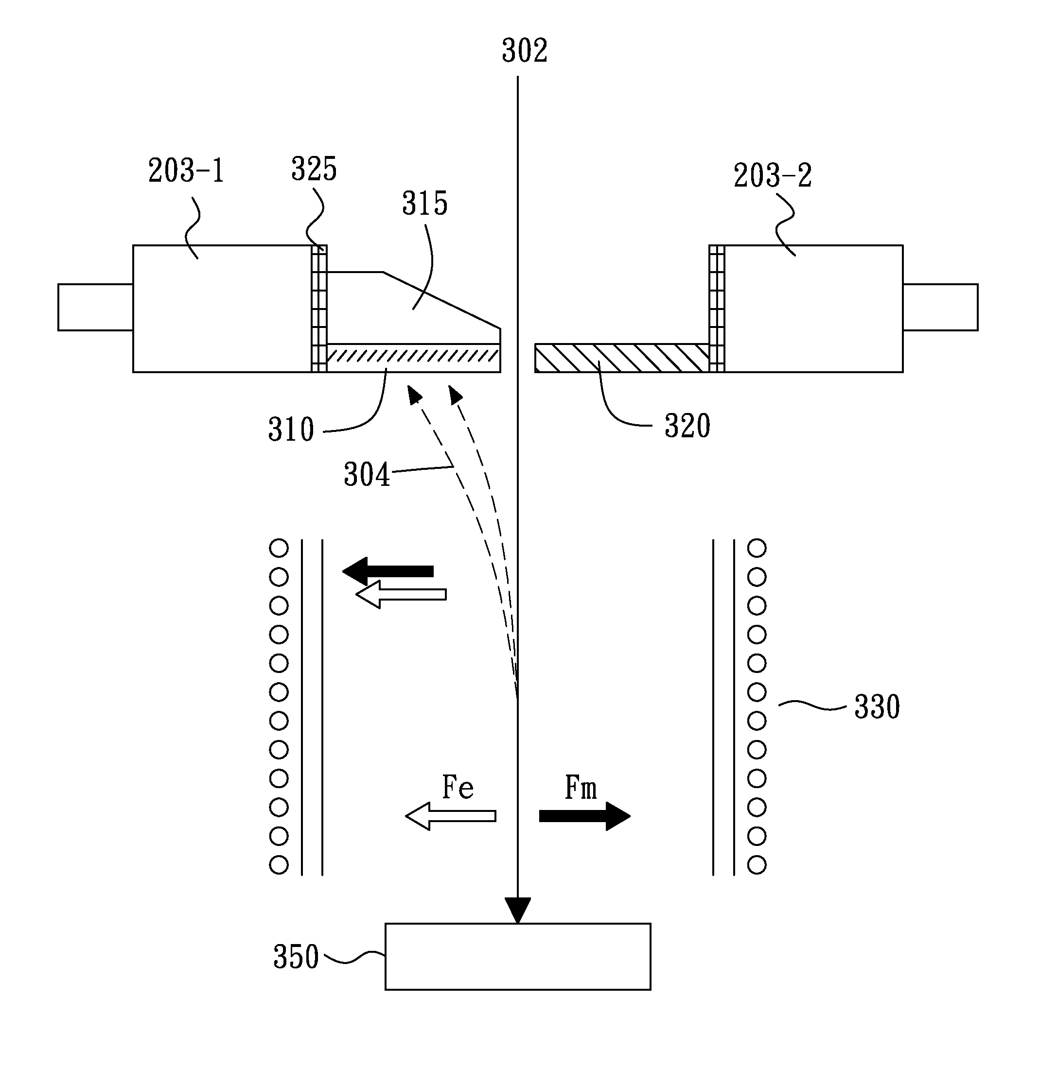
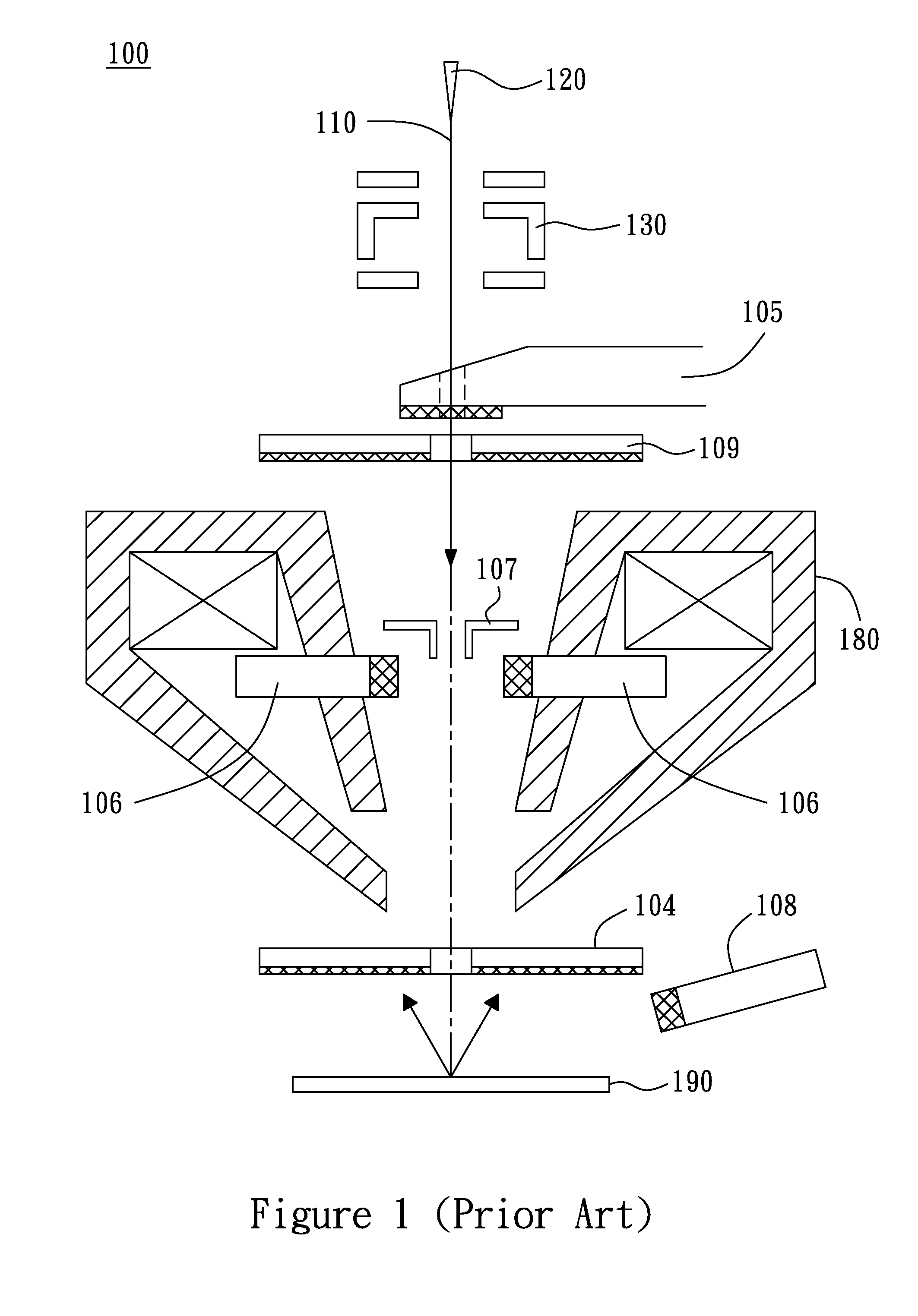
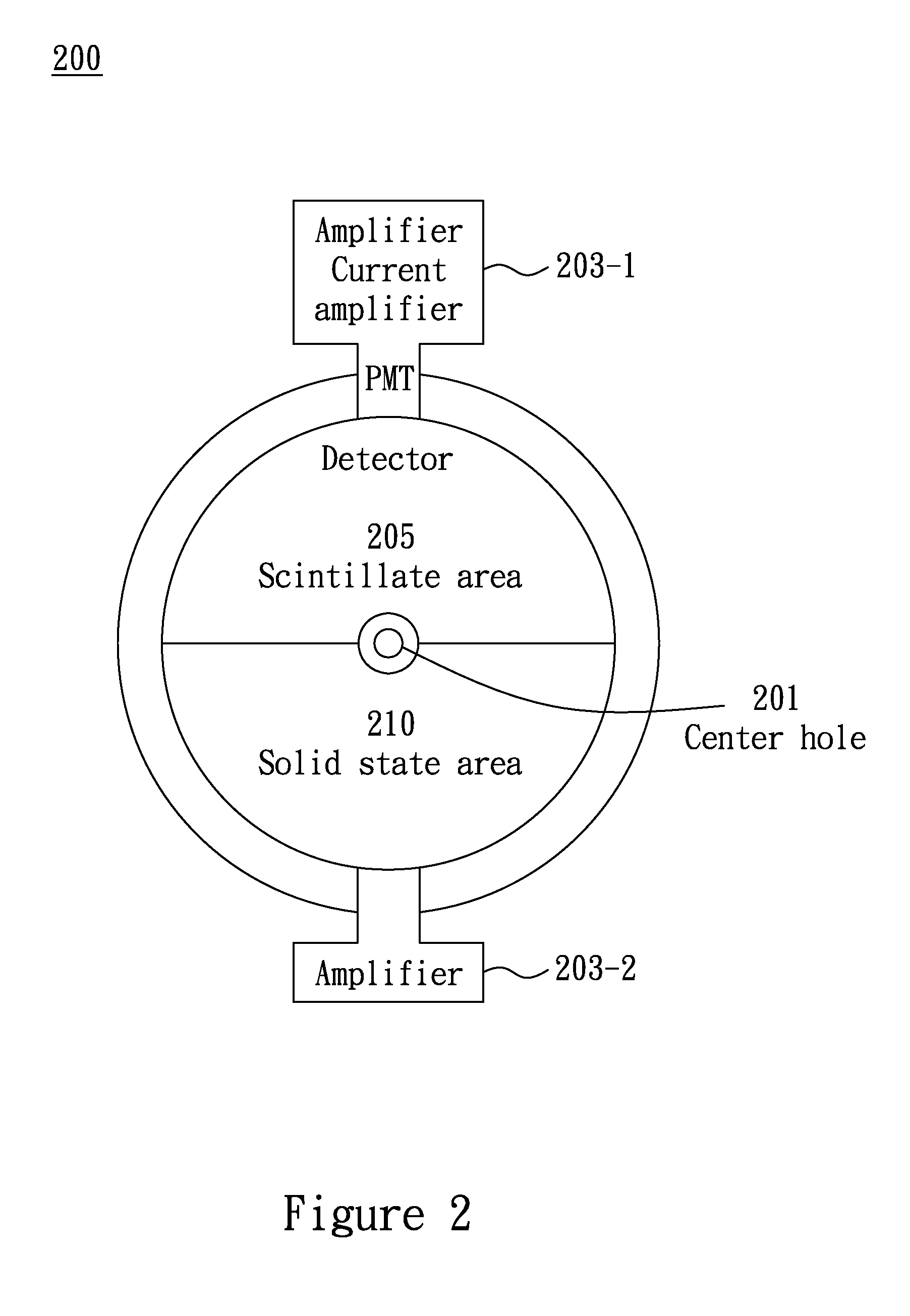
[0017]The present invention generally relates to a detection unit of a charged particle imaging system, and m...


PUM


Abstract

A detection unit of a charged particle imaging system includes a multi type detection subunit in the charged particle imaging system, with the assistance of a Wien filter (also known as an E×B charged particle analyzer). The imaging system is suitable for a low beam current, high resolution mode and a high beam current, high throughput mode. The unit can be applied to a scanning electron inspection system as well as to other systems that use a charged particle beam as an observation tool.

Description

FIELD OF THE INVENTION[0001]The present invention generally relates to a detection unit of a charged particle imaging system, and more particularly to a multi-detector in the charged particle imaging system.BACKGROUND OF THE INVENTION[0002]In order to lower the costs and improve the performance of ICs (integrated circuits), the design nodes of ICs should be made smaller. Shrinking of the design nodes to 22 nm or even smaller, however, makes the defect inspection tool, such as an optical system, less able to detect the defects, owing to the optical resolution of light sources used being equal to or larger than the defect dimension. For advancing resolution in defect inspection, a more applicable inspection tool, such as an e-beam inspection tool, is provided for semiconductor process inspections. Further, in a VC (voltage contrast) mode of inspection the e-beam inspection tool can inspect for under-layer defects, the performance of which is almost impossible for current-day optical i...

Claims


Application Information

Patent Timeline
Patent Type & Authority Patents(United States)
IPC IPC(8): H01J37/26
CPCG01N23/225G01N23/00G01N23/04H01J37/26H01J37/244H01J37/28H01J2237/24485H01J2237/2448H01J2237/2449H01J2237/24465H01J2237/24564H01J2237/24495H01J2237/24585H01J2237/24475
Inventor WANG, JOEZHANG, XUCHEN, ZHONGWEI
Owner ASML NETHERLANDS BV
Why Eureka
Try Eureka