Method of manufacturing a micromechanical part

a manufacturing method and technology of mechanical parts, applied in the field of manufacturing mechanical parts, can solve the problems of risk of damage to such parts, current manufacturing methods remain complex to implement, and it is not possible to apply micro-machinable materials to all timepiece parts, etc., to achieve high quality manufacturing, prevent any handling, and ensure the effect of pre-assembly

Active Publication Date: 2013-01-15
THE SWATCH GRP RES & DEVELONMENT LTD
View PDF6 Cites 10 Cited by
  • Summary
  • Abstract
  • Description
  • Claims
  • Application Information

AI Technical Summary

Benefits of technology

[0004]It is an object of the present invention to overcome all or part of the aforecited drawbacks by proposing a method that allows, simple, reliable pre-assembly of the part preventing any handling of the functional portions thereof so that the part is ready to be mounted in a device, such as a timepiece, without having to be touched. Moreover, the method allows high quality manufacture of a micromechanical part that can be applied to most mechanical timepiece parts.
[0016]step h) includes these steps: k) guiding the substrate relative to said base using alignment means so as to orient said substrate reliably and l) sliding the substrate against at least one pin secured to the support so that the substrate abuts against a shoulder of said at least one pin made at a distance from said support so as to keep the substrate high relative to said support;

Problems solved by technology

Thus, while it may be possible to manufacture balance springs, it is not yet possible to apply micro-machinable materials to all timepiece parts because of their insufficient tribological properties.
Moreover, current manufacturing methods remain complex to implement and require direct handling of the manufactured parts, at the risk of damage to such parts.

Method used


Image

  • Method of manufacturing a micromechanical part
  • Method of manufacturing a micromechanical part
  • Method of manufacturing a micromechanical part

Examples


first embodiment

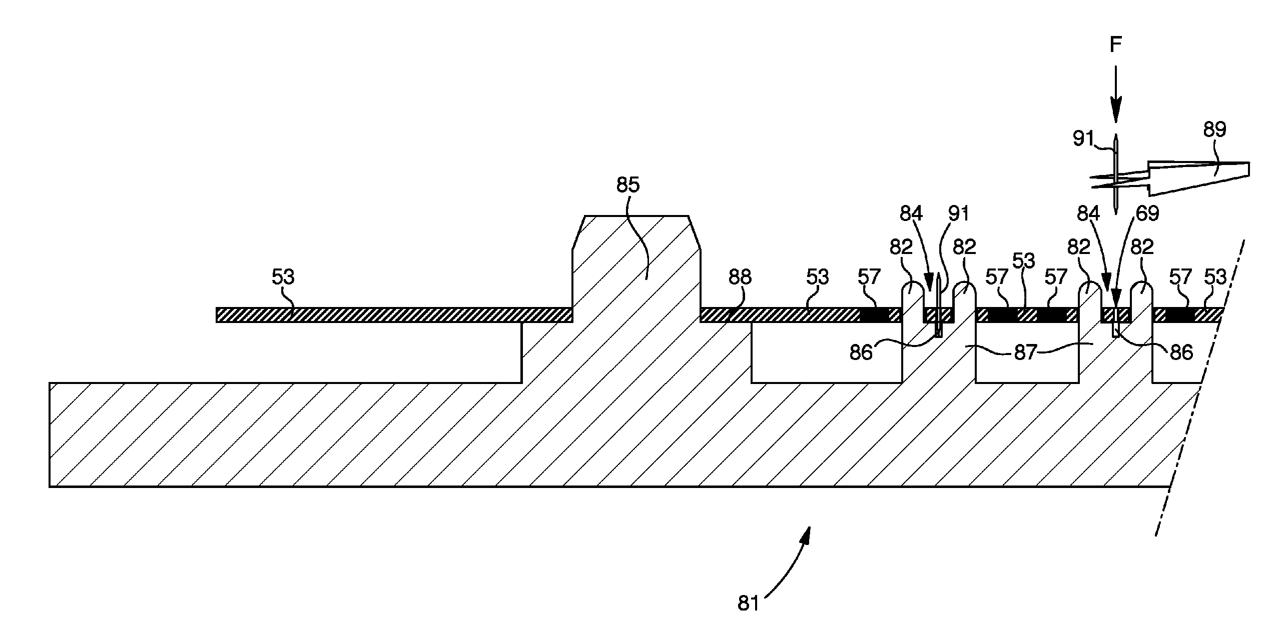
[0042]From the main steps 3, 5, 7, 9, 11 and 13 each of the embodiments will now be explained. In a first embodiment, method 1 includes the consecutive steps 3, 5, 13 and 11 illustrated by a single line in FIG. 7. The first step 3 consists in taking a substrate 53 made of micro-machinable material.

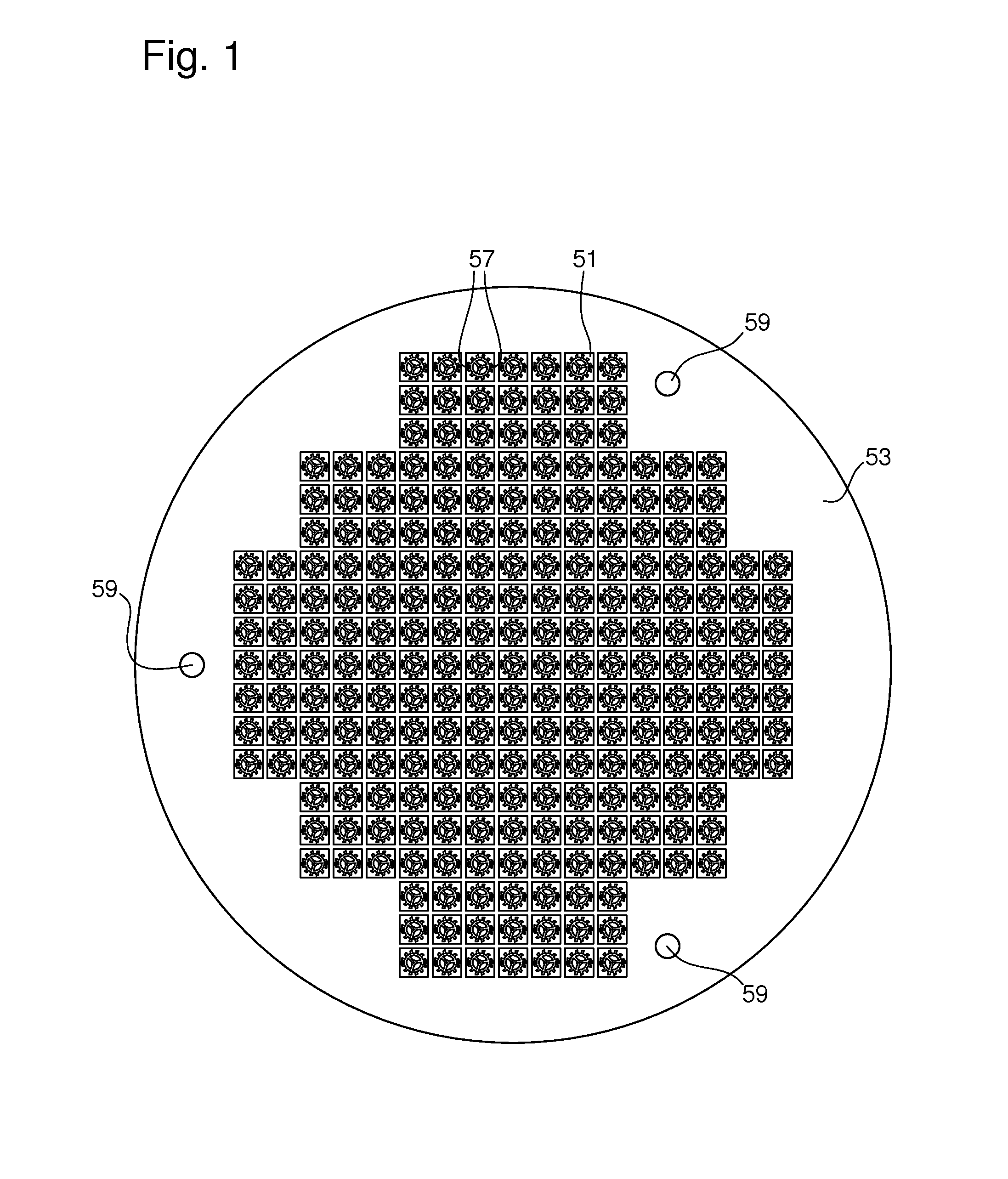
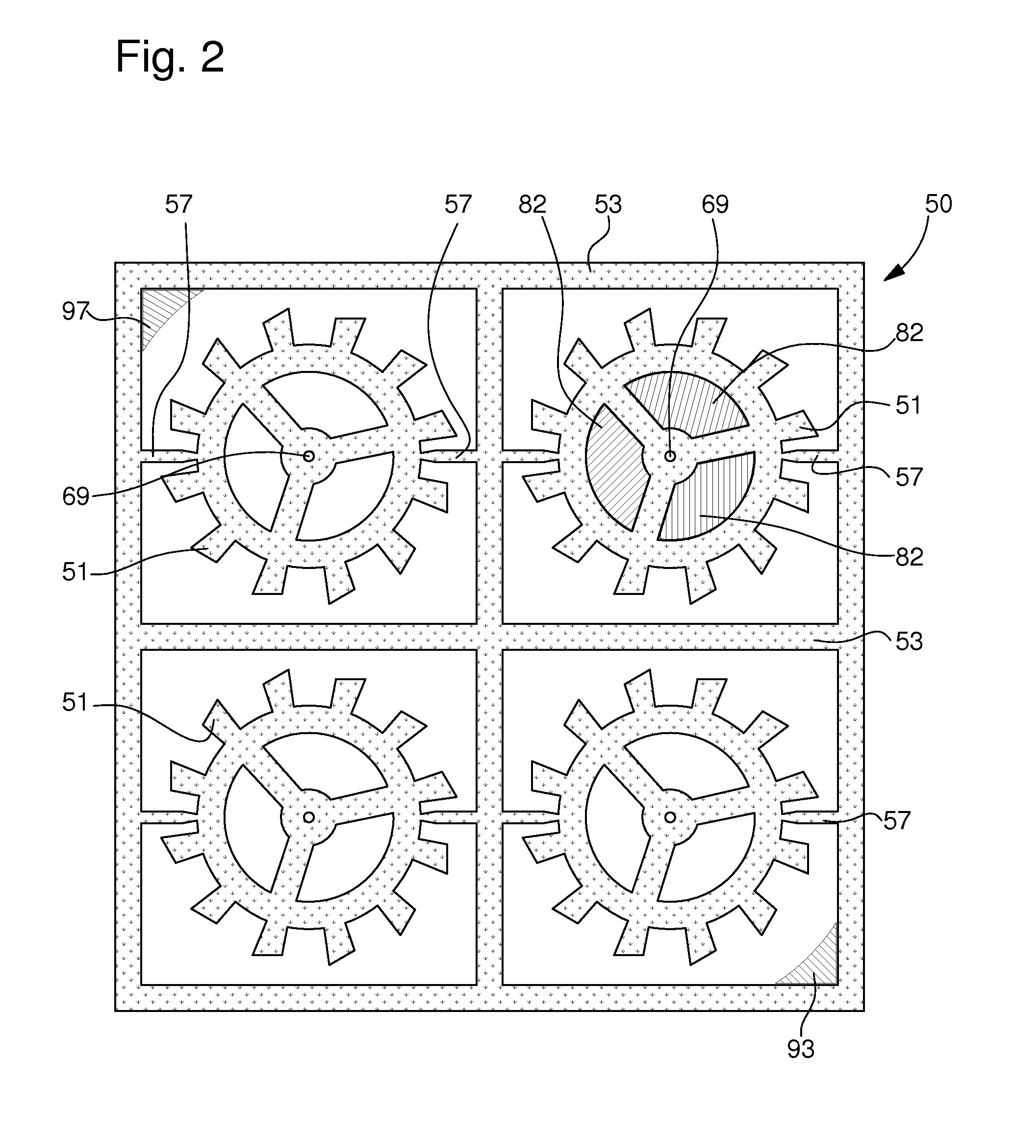
[0043]Then the second step 5 consists in making patterns 50, each including a mechanical part 51 to be manufactured, through the entire substrate 53 by photolithography then etching. According to the first embodiment illustrated in the flow chart of FIG. 7, the second step 5 includes three phases 15, 17 and 19.

[0044]In a first phase 15, a protective mask is structured on substrate 53. Preferably, the protective mask is made using a photosensitive resin. The protective mask is thus formed using selective radiation for structuring said mask in a shape corresponding to each pattern 50 to be made. Because of this step 15, it will be possible to etch any flat shape selectively on substrate 53 i...

second embodiment

[0062] the third step 7 consists in mounting the etched substrate 53 on a base 55 so as to leave the top and bottom surfaces of substrate 53 accessible in order to prepare for deposition step 9. Step 7 includes phases 21 and 23.

[0063]FIG. 3 illustrates an example base 55 according to the second embodiment. Base 55 is a plate, the material of which can withstand the temperatures of step 9, such as, for example, a ceramic. In order to keep substrate 53 high relative to base 55, the base has pins 61 for cooperating with holes 59 made in substrate 53 during step 5. For the same reasons as base 55, pins 61 are preferably made of tungsten or tantalum.

[0064]Preferably, each generally cylindrical pin 61 has a low part 63 connected to a high part 65 of smaller section by means of a shoulder 67. The low part 63 is mounted approximately perpendicularly in base 55 in a fixed manner. In the extension of the high part 65 there is a chamfered column 60 that belongs to alignment means cited below.

[...


PUM

PropertyMeasurementUnit
thicknessaaaaaaaaaa
photosensitiveaaaaaaaaaa
tribological qualityaaaaaaaaaa

Abstract

A method of manufacturing a mechanical part includes providing a substrate of micro-machinable material; etching, using photolithography, a pattern that includes said part through said entire substrate; assembling a clip on said part so that said part is ready to be mounted without the portion made of micro-machinable material having to be touched by a tool other than the clip; releasing the part from the substrate so as to mount said part in a device such as a timepiece movement.

Description

[0001]This application claims priority from European Patent Application No. 08160143.7 filed Jul. 10, 2008, the entire disclosure of which is incorporated herein by reference.FIELD OF THE INVENTION[0002]The invention relates to a method of manufacturing a mechanical part made from a micro-machinable material and, more specifically, a part of this type that will be used for manufacturing a timepiece.BACKGROUND OF THE INVENTION[0003]Manufacturing a timepiece part in a crystalline, silicon-based material is known. Indeed, the use of a micro-machinable like crystalline silicon has advantages in terms of manufacturing precision, owing to advances in current methods particularly within the electronics field. Thus, while it may be possible to manufacture balance springs, it is not yet possible to apply micro-machinable materials to all timepiece parts because of their insufficient tribological properties. Moreover, current manufacturing methods remain complex to implement and require direc...

Claims


Application Information

Patent Timeline
Patent Type & Authority Patents(United States)
IPC IPC(8): C23F1/00
CPCB81C3/008B81C99/008G04D3/0069G04B13/026B81B2201/035Y10T29/49581Y10T29/49579G04B13/02G04B15/14G04D1/00G04D3/002G04D3/0033G03F7/0002B81C2201/112
Inventor DINGER, RUDOLFRAVENEL, THIERRY
Owner THE SWATCH GRP RES & DEVELONMENT LTD
Why Eureka
Try Eureka