
Layout structure of non-volatile memory device

a non-volatile memory and layout structure technology, applied in semiconductor devices, digital storage, instruments, etc., can solve the problems of high cost, poor device yield, and complicated manufacturing process of embedded memory devices using double-poly non-volatile memory devices, so as to reduce the leakage current produced at the corners of isolation structures, reduce the coupling efficiency, and reduce the effect of corners

Active Publication Date: 2013-01-29
UNITED MICROELECTRONICS CORP
View PDF14 Cites 1 Cited by
  • Summary
  • Abstract
  • Description
  • Claims
  • Application Information

AI Technical Summary

Benefits of technology

The present invention relates to a non-volatile memory cell that reduces leakage currents at the corners of isolation structure and achieves higher coupling efficiency of the capacitor. A layout structure of the non-volatile memory device improves programming speed and device density, and reduces leakage currents while increasing coupling efficiency of the capacitor. Additionally, the layout structure allows for one word line to control four bit lines and increases device density.

Problems solved by technology

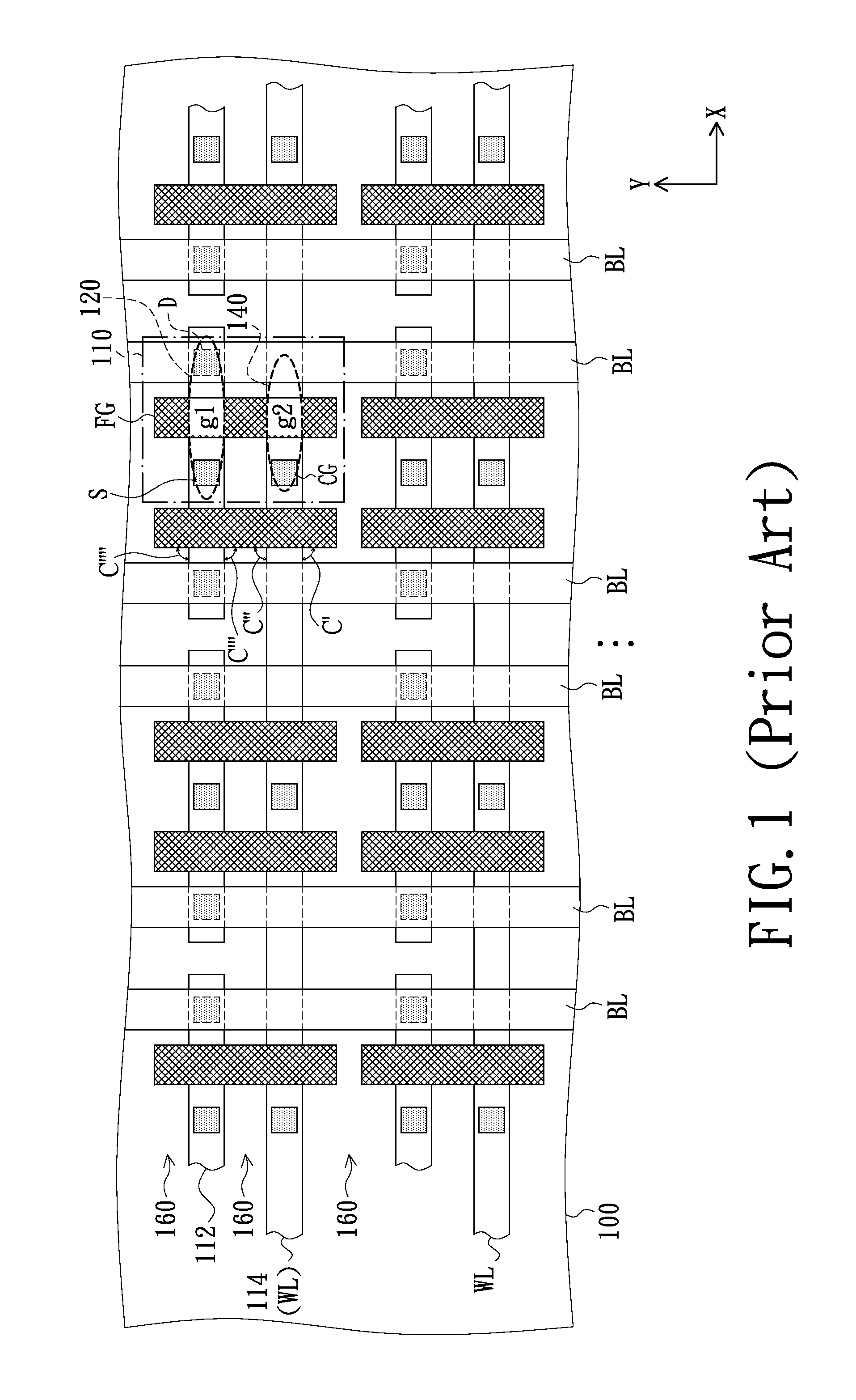
However, in an advanced logic process, the manufacturing process of the embedded memory devices by using the double-poly non-volatile memory devices is more complicated and has high cost, the device yield is also not good.
Therefore, how to achieve the above-mentioned aims will be one of important issues for the development of memory device.

Method used


Image

  • Layout structure of non-volatile memory device
  • Layout structure of non-volatile memory device
  • Layout structure of non-volatile memory device

Examples


Embodiment Construction

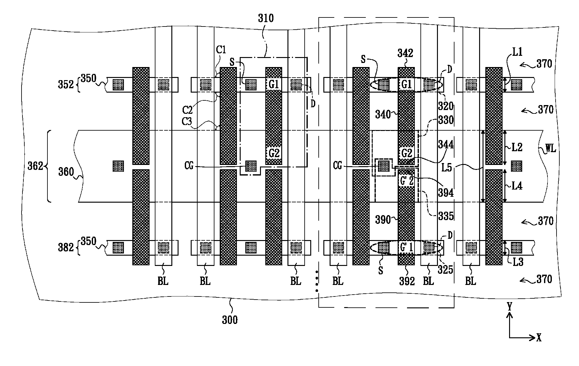
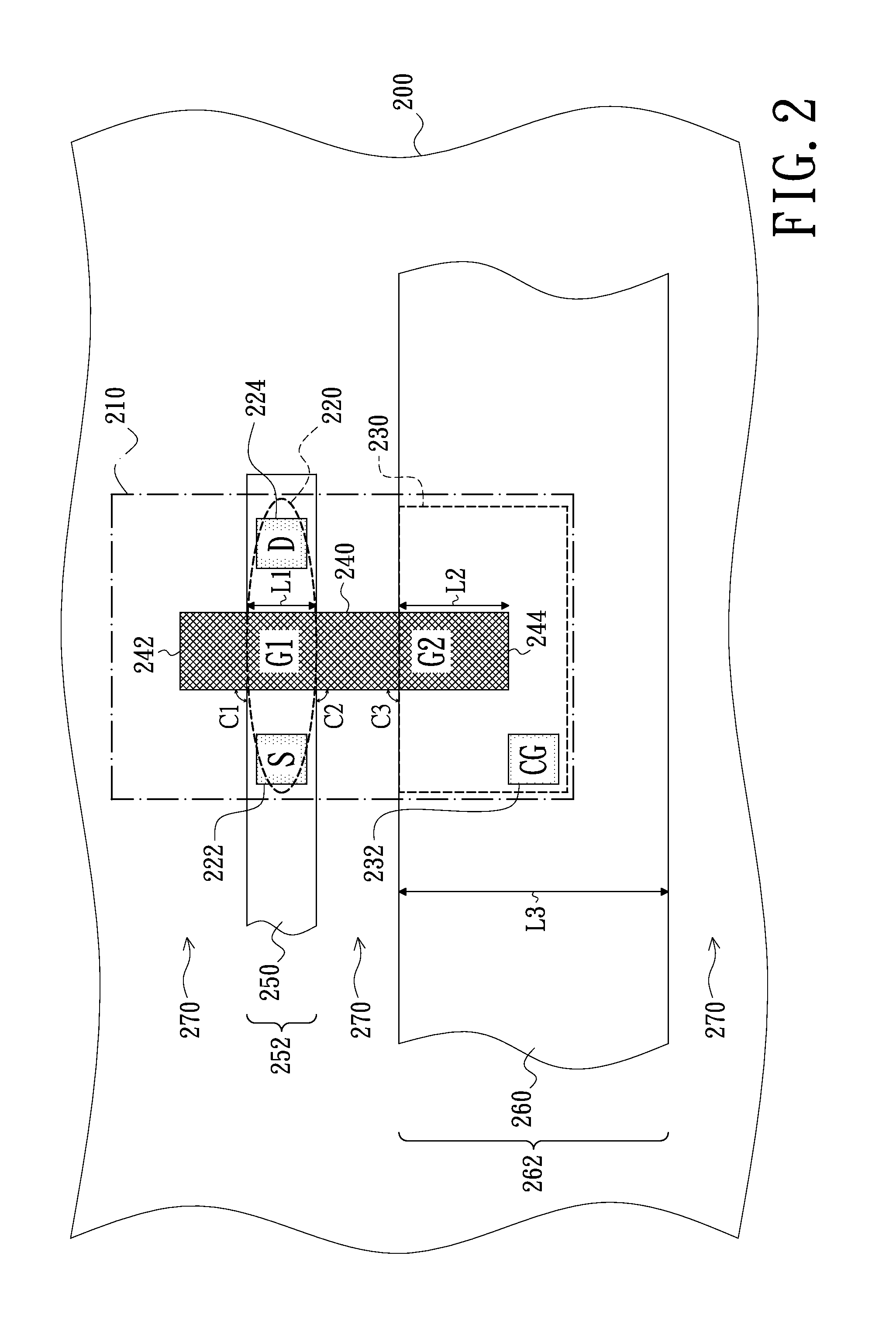
[0035]FIG. 2 is a schematic top view of a non-volatile memory cell in accordance with an embodiment of the present invention.

[0036]As illustrated in FIG. 2, the non-volatile memory cell 210 is comprised of a semiconductor substrate 200, a conductor 240, a plurality of isolation structures 270, a first-type doped well 260, two first ion doped regions 222, 224 and a second ion doped region 232.

[0037]The semiconductor substrate 200 has the isolation structures 270 arranged in parallel with one another and disposed therein. The isolation structures 270 are for example shallow trench isolation (STI) structures. The isolation structures 270 define a transistor region 252 and a capacitor region 262 in parallel with the transistor region 252 in the semiconductor substrate 200. The first-type doped well 260 is disposed in the capacitor region 262 and is for example an N-type doped well.

[0038]In the illustrated embodiment, the semiconductor substrate 200 is for example a non-doped semiconduct...


PUM


Abstract

A non-volatile memory cell includes a semiconductor substrate with isolation structures formed therein and thereby transistor region and capacitor region are defined therein. A conductor is disposed over the isolation structures, the transistor region and a first-type doped well disposed in the capacitor region. The conductor includes a capacitor portion disposed over the first-type doped well, a transistor portion disposed over the transistor region, a first edge disposed over the isolation structure at a side of the transistor region, and an opposite second edge disposed over the first-type doped well. Two first ion doped wells are disposed in the transistor region and respectively at two sides of the transistor portion, and constitutes a transistor with the transistor portion. A second ion doped region is disposed in the capacitor region excluding the conductor and constitutes a capacitor with the capacitor portion.

Description

BACKGROUND[0001]1. Technical Field[0002]The present invention generally relates to a semiconductor device and a layout structure thereof and, more particularly to a non-volatile memory cell and a layout structure of non-volatile memory device.[0003]2. Description of the Related Art[0004]Non-volatile memory (NVM) devices have the advantage of stored data would not disappear even when power supplied thereto is interrupted, and therefore have become one of widespread memory devices for data storage.[0005]According to read-write cycle limits of memory devices, the non-volatile memory devices are classified into one type of multi-time programmable (MTP) memory device having repeatable read / write functionality and another type of one-time programmable (OTP) memory device only can be written a single time with data. In another aspect, from the viewpoint of device structure, the non-volatile memory devices primarily can be classified into double-poly non-volatile memory devices and single-p...

Claims


Application Information

Patent Timeline
Patent Type & Authority Patents(United States)
IPC IPC(8): H01L27/108H01L29/66H10B12/00
CPCH01L27/0207H01L27/11519H01L27/11558H01L29/66825H01L29/7881H10B41/10H10B41/60
Inventor SHIH, HUNG-LINCHEN, JR-BINYIN, PEI-CHINGTSAI, HUI-FANG
Owner UNITED MICROELECTRONICS CORP
Learn More