
Combustion of oil floating on water

Inactive Publication Date: 2013-02-05
AIR PROD & CHEM INC
View PDF19 Cites 10 Cited by
  • Summary
  • Abstract
  • Description
  • Claims
  • Application Information

AI Technical Summary

Benefits of technology

The patent describes a method for controlling the rate at which oil burns by adjusting the amount of oxygen introduced near the oil layer. This can be done by using oxygen-containing gas to quench the combustion of the oil. The technical effect of this method is to allow for better control over the oil combustion process, which can improve safety and efficiency in various applications such as industrial cleaning or machining.

Problems solved by technology

The BP oil spill in the Gulf of Mexico resulted in large areas of crude oil floating on the ocean surface.
The problem of burning oil in the ocean surface is that favorable combustion conditions are rarely achievable, particularly towards the center of the fire where oxygen availability is limited due to lack of air entrainment.
But its use is not approved due to high cost, difficulty of applying, and potential toxicity.
While the black smoke may have less environmental impact than the oil slick, the public generally finds the black smoke plume objectionable.
A further problem of the in-situ burn is that a substantial amount of oil is still left unburned after the fire self-extinguishes, that is, after a minimum flame-sustainable oil layer thickness is reached as reported in the Coast Guard Manual.
Another problem with oil floating on water is the formation of a stable water-in-oil emulsion which will reduce the window of opportunity for in-situ burning.

Method used


Image

  • Combustion of oil floating on water
  • Combustion of oil floating on water
  • Combustion of oil floating on water

Examples


examples

[0088]Laboratory scale experiments were conducted. Experiments were conducted using a 10 cm diameter container and a 20 cm diameter container. The 10 cm diameter container provides a turbulent flame with convective heat transfer feedback. The 20 cm diameter container provides a turbulent flame which is in the transition region for radiant heat transfer feedback, as in a large pool fire. Number 2 fuel oil was used as the flammable liquid.

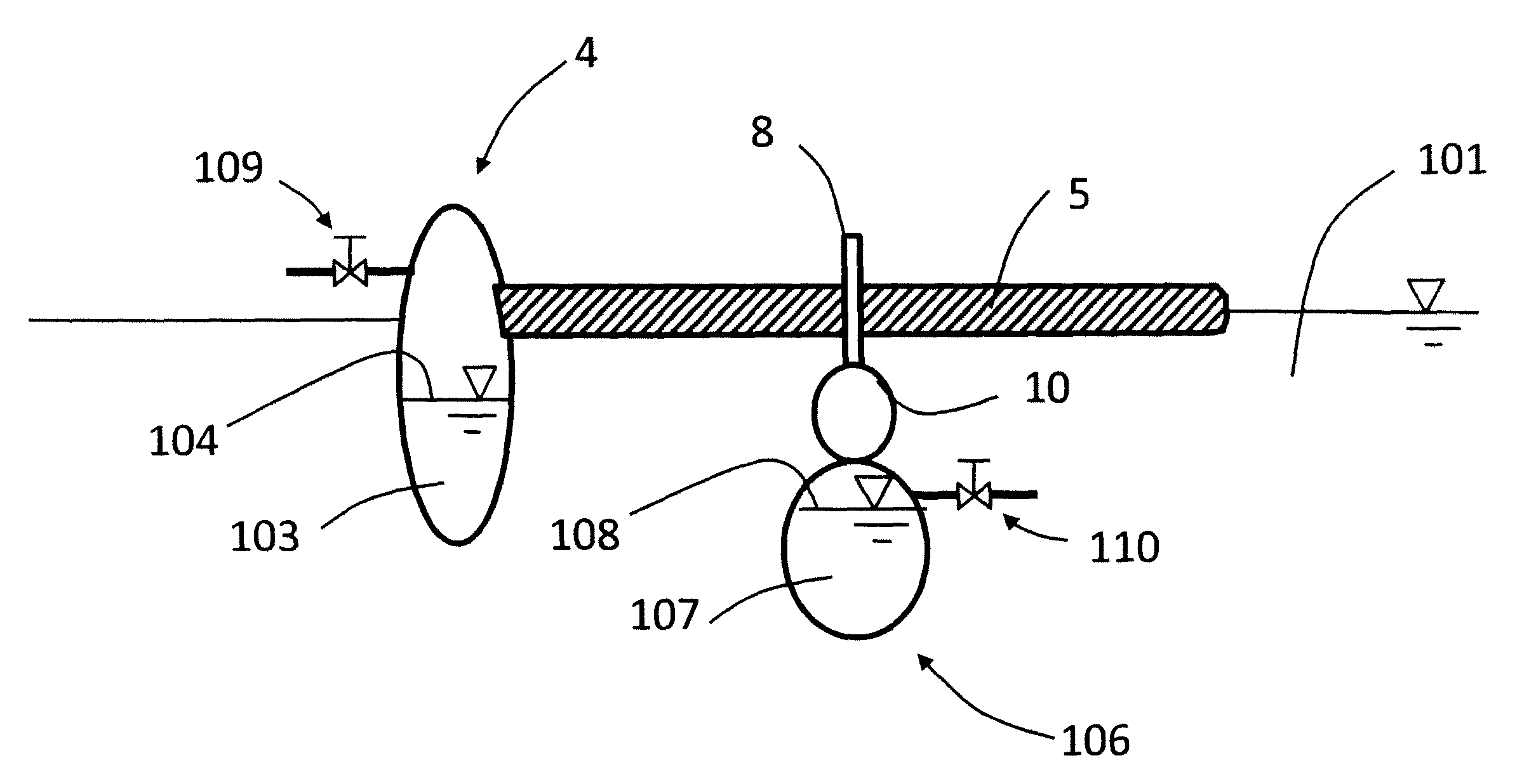
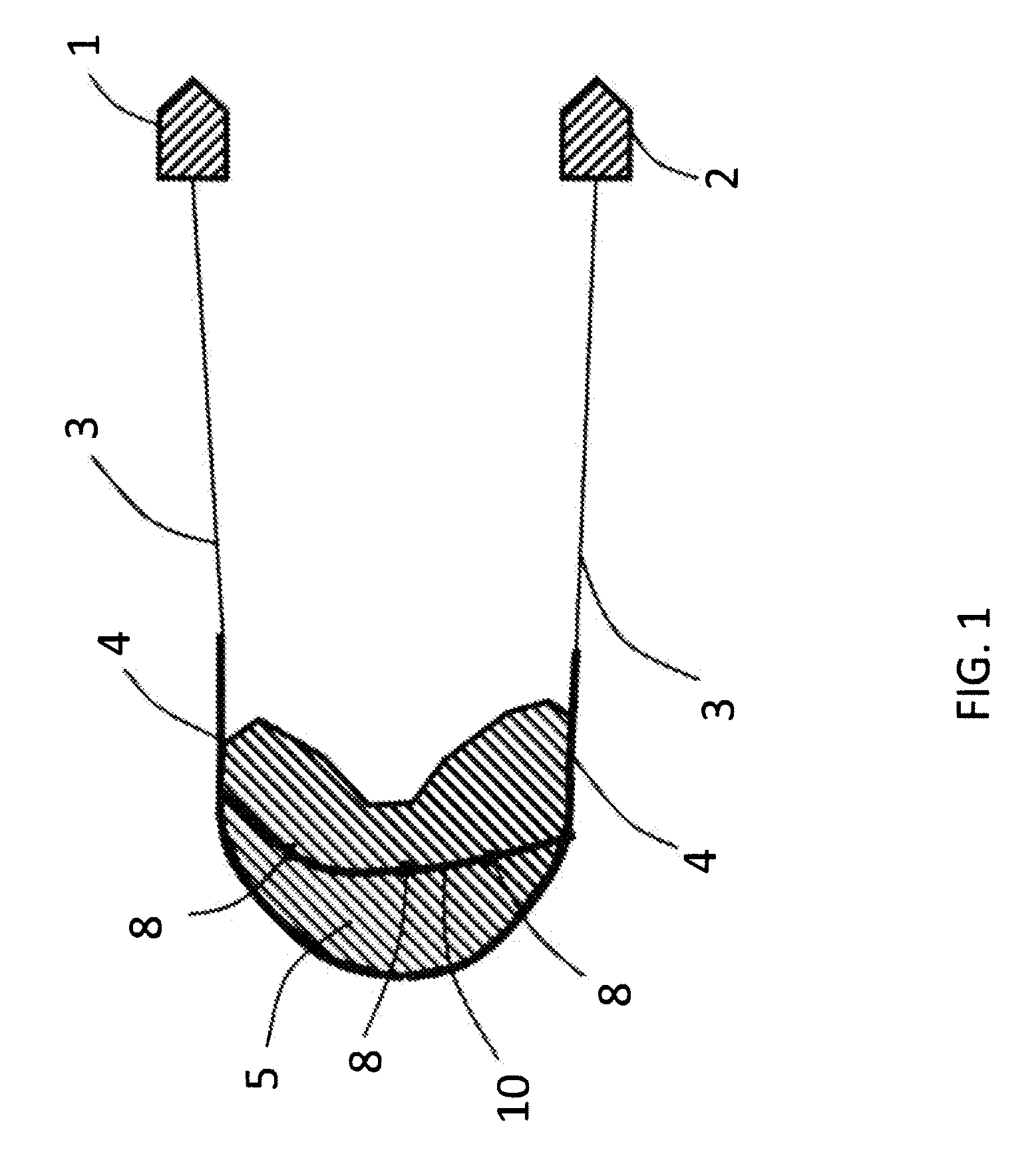
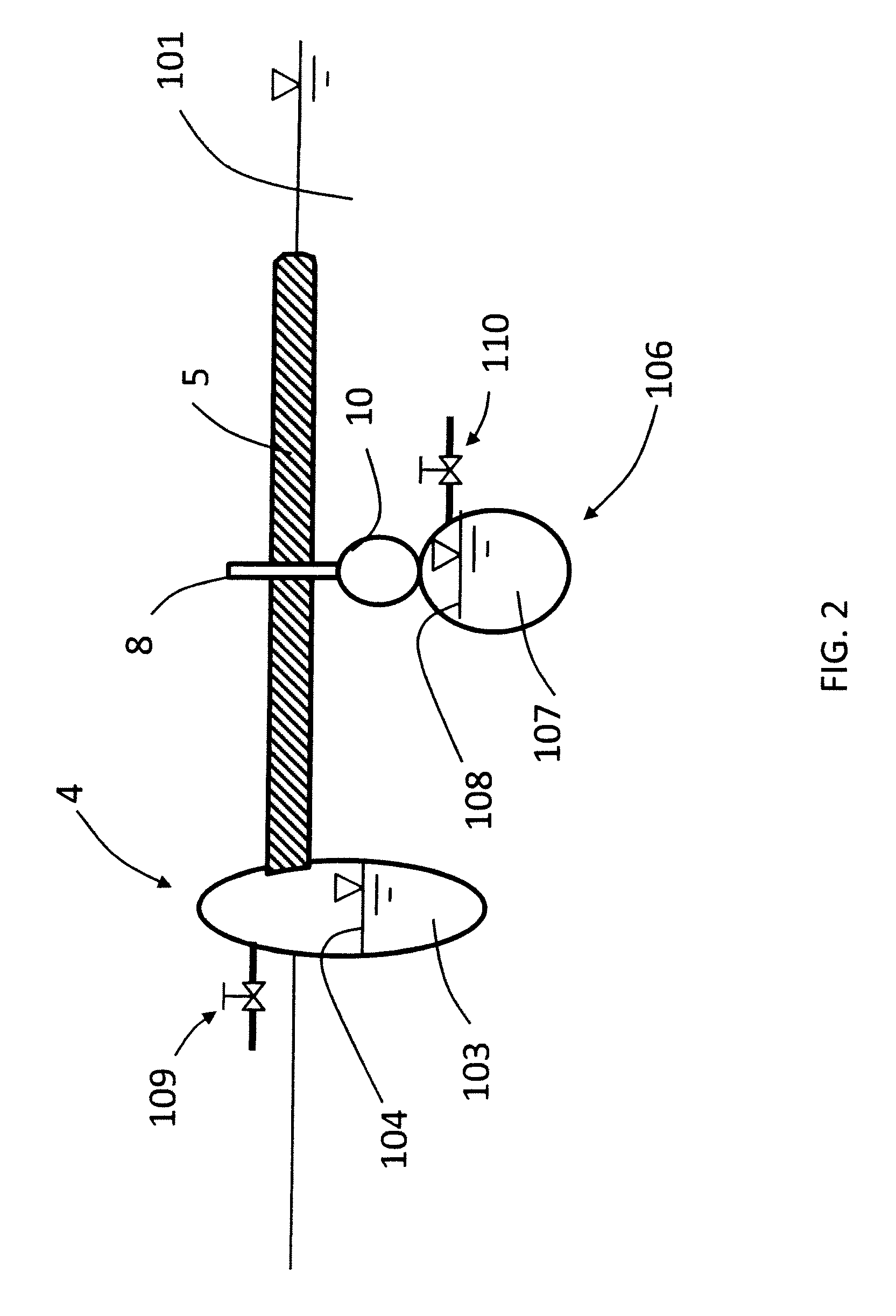
[0089]Both the 10 cm container and the 20 cm diameter container are 20 cm tall. Approximately 17.5 cm of the container was filled with water, and up to 2.5 cm of No. 2 fuel oil was floated on top of the water. An oxidant injection tube was placed near the center of the container. The tube was capped at the end. Six orifices were drilled on the side of the tube near the cap to inject oxidant substantially horizontally across the oil surface, and one orifice was drilled through the center of the cap to inject oxidant substantially upward as illustrated...


PUM


Abstract

A method for combusting oil from an oil-containing layer floating on water as from an oil spill or well leak. In the method, an oxygen-containing gas is passed through a conduit, the oxygen-containing gas from the conduit is introduced proximate the oil-containing layer floating on water, and oil from the oil-containing layer is combusted with the oxygen-containing gas in the presence of a flame. The oxygen-containing gas is introduced with an oxygen molar flow rate sufficient to decrease the opacity of a smoke plume from the combusting oil.

Description

BACKGROUND[0001]The BP oil spill in the Gulf of Mexico resulted in large areas of crude oil floating on the ocean surface. Some of these areas are close to beaches or natural habitats of animals. Mechanical recovery, chemical treatment, bioremediation, and in-situ burning are amongst the most widely practiced marine oil spill response technologies.[0002]While large scale skimming is one method to control oil pollution, the U.S. Coast Guard has been conducting in-situ burns of the surface oil, primarily due to the advantages associated with this technology such as high oil removal rates, relatively low cost, and simple logistics.[0003]The U.S. Coast Guard issued an operations manual for in-situ burning of oil from oil spills as U.S. Coast Guard Research and Development Center Report No. CG-D-06-03, Oil Spill Response Offshore, In-Situ Burn Operations Manual, Final Report, March 2003 (hereinafter, Coast Guard Manual). The Coast Guard Manual may be referred to for conventional in-situ ...

Claims


Application Information

Patent Timeline
IPC IPC(8): F23C5/00E02B15/04F23C99/00
CPCE02B15/042F23G7/05F23L7/007Y02E20/344F23L2900/07007Y02A20/204Y02E20/34
Inventor ASHLINE, PAUL M.YING, DAVID HON SINGGORUNEY, TUNCLI, XIANMING JIMMYJOHNSON, LEIGHTA MAUREEN
Owner AIR PROD & CHEM INC
Learn More