
Image-guided minimal-step placement of screw into bone

a technology of screw and bone, which is applied in the field of image-guided minimal-step placement of screw into bone, can solve the problems of patient paralysis or death, the risk of surgery, and the long and costly surgery currently performed in the spine surgical procedure,

Active Publication Date: 2013-02-05
INTEGRATED SPINAL CONCEPTS
View PDF36 Cites 632 Cited by
  • Summary
  • Abstract
  • Description
  • Claims
  • Application Information

AI Technical Summary

Benefits of technology

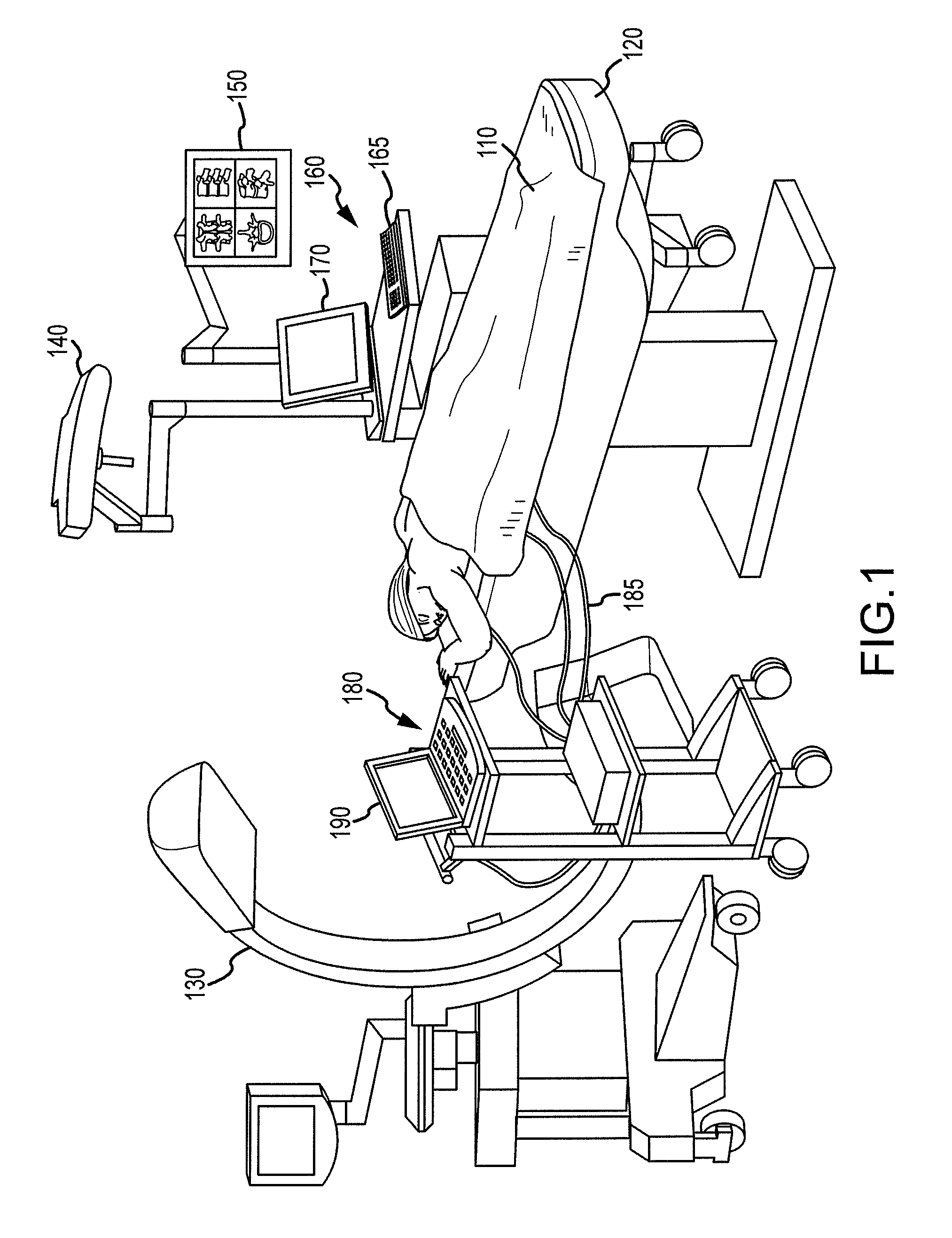
The present patent describes devices and methods for placing screws into bones, particularly in spinal surgery. These devices allow for powered insertion of screws with unprecedented accuracy, precision, and safety. The methods eliminate many of the limitations and detriments of current procedures, resulting in decreased surgical time, reduced patient-recovery time, and decreased associated medical costs. The devices and methods integrate with image-guidance systems, providing precision of screw placement without repeated verification of a planned trajectory associated with manual insertion. Overall, the technology revolutionizes spinal-fixation procedures and other delicate surgical procedures.

Problems solved by technology

Surgical procedures involving the bones of the spine are among the most dangerous, lengthy, and costly surgeries presently performed.
A primary reason that these surgeries are so dangerous is due to the proximity of the spinal bones to the spinal cord.
Thus, even slight miscalculations and inaccuracies during a spinal procedure may have devastating results, including patient paralysis or death.
Consequently, spinal surgeries involve meticulous care and multiple safeguards and precautions—resulting in extremely time-consuming procedures.
Although precision and accuracy are paramount, lengthy procedures are associated with additional risks and dangers.
Finally, the length of a surgical procedure is directly linked to the cost of that surgical procedure.
This redundancy, while potentially increasing precision on the one hand, may increase the opportunity for clinician error, device malfunction, and device contamination on the other.
In addition, as noted above, because surgical time is greatly increased by this multi-step procedure, patient recovery time, risk of infection, and associated medical costs are also correspondingly increased.
Indeed, associated medical costs may be compounded by both increased surgical time and staffing in hospital facilities and by increased hospital stays due to the increased patient recovery time and complications brought on by secondary infections.
Further, as the present procedures are dependent on manual rotation for placement of the screw, inaccurate screw placement in patients with diseased bone or uncharacteristic anatomical landmarks may also be increased, along with a high probability of multiple X-rays to confirm accurate screw placement.
That is, by employing multiple layers of fail-safe features, the powered driving devices arguably exceed present multi-step procedures in safety.
Indeed, by eliminating many of the redundant verification steps, the methods provide a decreased opportunity for clinician error, decreased opportunity for device contamination, and decreased surgical time with associated decreased patient-recovery time and decreased associated medical costs.

Method used


Image

  • Image-guided minimal-step placement of screw into bone
  • Image-guided minimal-step placement of screw into bone
  • Image-guided minimal-step placement of screw into bone

Examples


first embodiment

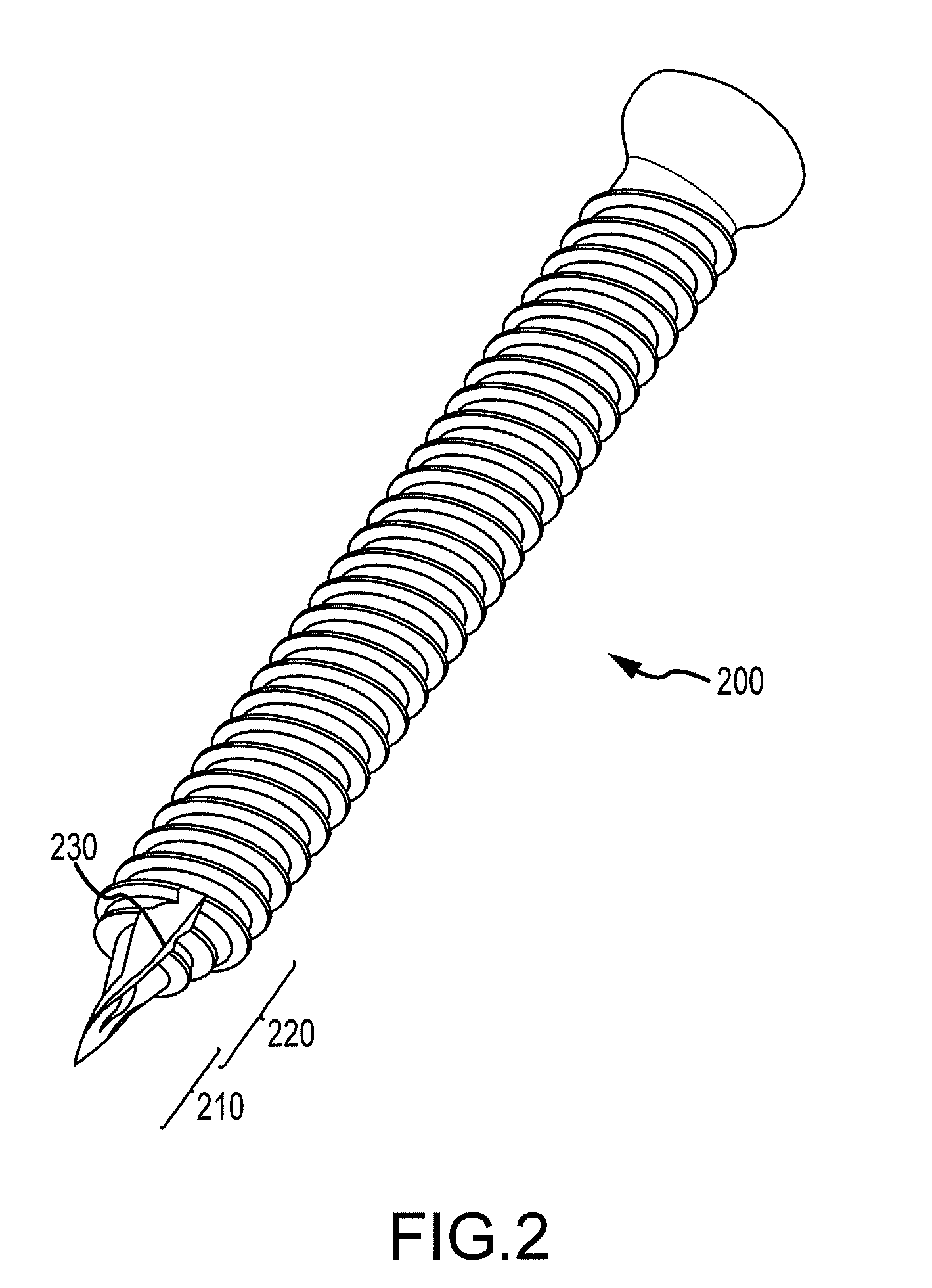
[0050]FIG. 2 is an illustration of a specialized screw as described herein.

[0051]Specialized screw 200 illustrates a first embodiment of a specialized self-drilling, self-tapping screw. A specialized screw may refer to any suitable screw that may be used in combination with a powered driving device, as described herein, for insertion into bone. Further, suitable screws may or may not comprise each feature of the described embodiment, e.g., specialized screw 200, including described self-drilling and / or self-tapping features. That is, other suitable screw designs may be inserted into bone via a powered driving device as disclosed herein and may be included within the scope of the present disclosure.

[0052]According to embodiments, specialized screw 200 may be made of any suitable, non-toxic, material for insertion into a bone. Suitable materials may include, but are not limited to, titanium and stainless steel. Specialized screw 200 may further include a plurality of screw portions. F...

second embodiment

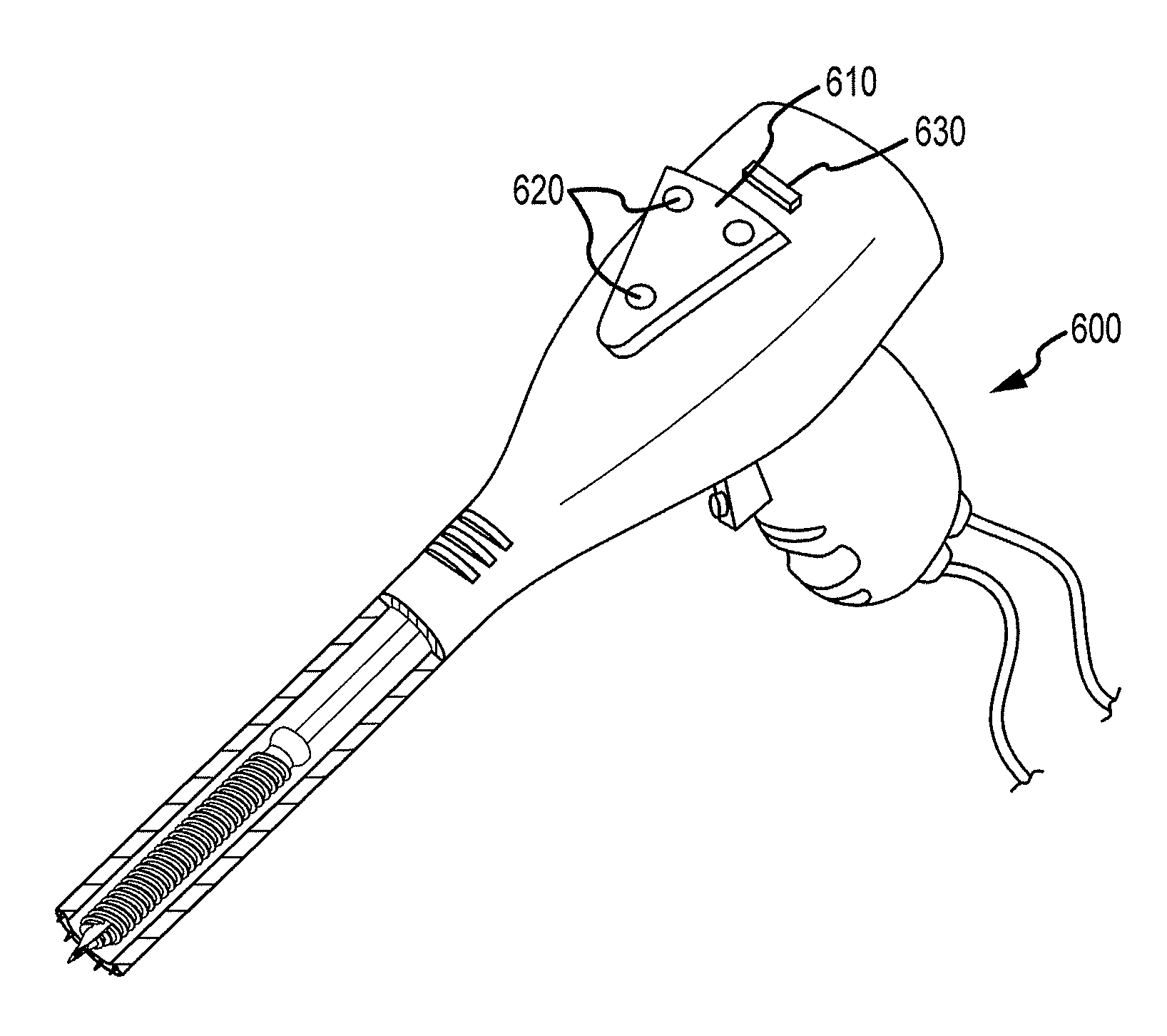
[0095]FIG. 5 is an illustration of a powered driving device as described herein.

[0096]According to embodiments, the second embodiment of a powered driving device, e.g., powered driving device 500, may be substantially similar to powered driving device 400. According to some embodiments, FIG. 5 provides additional illustrative description for features not visible in FIG. 4.

[0097]According to embodiments, powered driving device 500 may comprise any suitable powered driving device for accurately inserting a specialized screw into a bone. As described above, powered driving device 500 may further comprise an elongated, cylindrical drive chamber 510. According to embodiments, drive chamber 510 may be adjustable or otherwise altered for accommodating various types and sizes of specialized screws, as with drive chamber 410. According to alternative embodiments, a plurality of different sized drive chambers 510 may be manufactured corresponding to particular specialized screw types and size...

third embodiment

[0171]FIG. 11 is a flow-diagram illustrating a method for automatically shutting down a powered driving device during screw placement.

[0172]At initiate operation 1102, after verification of a projected placement of the specialized screw using the image-guidance system or otherwise, the powered driving device may be initiated, as described above.

[0173]At monitor operation 1104, a position of the specialized screw may be monitored by sensors during insertion of the specialized screw. For example, according to embodiments, suitable sensors may be employed to detect a bone density around the specialized screw. As a bone density of the cortical layer may be greater than a bone density of the trabecular layer, bone density may be used to indicate that a specialized screw is approaching the cortical layer and is in danger of traversing and / or fracturing the bone. Alternatively, other suitable sensors may be employed to detect a proximity of the specialized screw to the cortical layer via a...


PUM


Abstract

The present disclosure describes a device and methods for safely and accurately placing screws into bones with a powered driving device. By employing multiple layers of fail-safe features and image-guidance systems, the powered driving device provides safe, accurate, and efficient screw placement. That is, the powered driving device may continuously monitor a screw advancement and placement and may automatically shutdown when improper placement is detected. Monitoring placement may be conducted by a microcurrent-monitoring system, by an image-guidance system, or by any other appropriate sensory system. Additionally, upon detecting that screw insertion is complete, the powered driving device may be automatically shutdown. As screw placement is continuously simulated by image-guidance in real time, multiple redundant verification steps are eliminated, providing highly accurate screw placement while decreasing clinician error, device contamination, and surgical time, the decreased surgical time associated with decreased patient-recovery time and associated medical costs.

Description

CROSS-REFERENCE TO RELATED APPLICATIONS[0001]This application claims the benefit of U.S. Provisional Application Ser. No. 61 / 161,332, filed Mar. 18, 2009, the complete disclosure of which is hereby incorporated by reference in its entirety.INTRODUCTION[0002]Surgical procedures involving the bones of the spine are among the most dangerous, lengthy, and costly surgeries presently performed. A primary reason that these surgeries are so dangerous is due to the proximity of the spinal bones to the spinal cord. Thus, even slight miscalculations and inaccuracies during a spinal procedure may have devastating results, including patient paralysis or death. Consequently, spinal surgeries involve meticulous care and multiple safeguards and precautions—resulting in extremely time-consuming procedures. Although precision and accuracy are paramount, lengthy procedures are associated with additional risks and dangers. In fact, studies have found a direct relationship between surgical time and pati...

Claims


Application Information

Patent Timeline
Patent Type & Authority Patents(United States)
IPC IPC(8): A61B17/00A61B17/58A61F2/00A61B17/14A61B17/32A61B17/60
CPCA61B17/8875A61B17/1626A61B17/1671A61B19/46A61B2017/00022A61B90/06A61B17/1622A61B17/7001A61B17/7076A61B2017/00026A61B2017/00123A61B2034/102A61B2034/107A61B34/20A61B2034/2051A61B2034/2055A61B2034/2065A61B17/1757A61B17/8635
Inventor MARKEY, SEANGEIGER, CHRIS
Owner INTEGRATED SPINAL CONCEPTS
Learn More