
Carbon phenolic ablative gap filler

Active Publication Date: 2013-02-05
LOCKHEED MARTIN CORP
View PDF9 Cites 10 Cited by
  • Summary
  • Abstract
  • Description
  • Claims
  • Application Information

AI Technical Summary

Benefits of technology

The invention provides a strong gap filler material for use in heat shield applications. It consists of a carbon phenolic composition, which can be in powder or particle form, and can easily fill the gaps between tiles or cells in ablative heat shields for spacecraft. This composition is compatible with existing carbon phenolics and PICA ablative heat shields, and can be applied in dry or wet form. It ablates at a controlled rate and does not cause any damage to the heat shield assembly during atmospheric entry.

Problems solved by technology

One issue with these RTV silicone-type materials is that they exhibit a very high coefficient of thermal expansion when compared to the ablative tile materials the gaps between which they are used to fill.
Therefore, during heating (e.g., during re-entry and thermal soakback conditions), the expansion and contraction of the gap filler material, particularly where it has bonded with adjacent tiles, can trigger the dislodging or chipping of the adjacent tiles, negatively impacting the smooth outer surface (and thereby the performance) of the ablative heat shield material.

Method used


Image

  • Carbon phenolic ablative gap filler
  • Carbon phenolic ablative gap filler

Examples


example 1

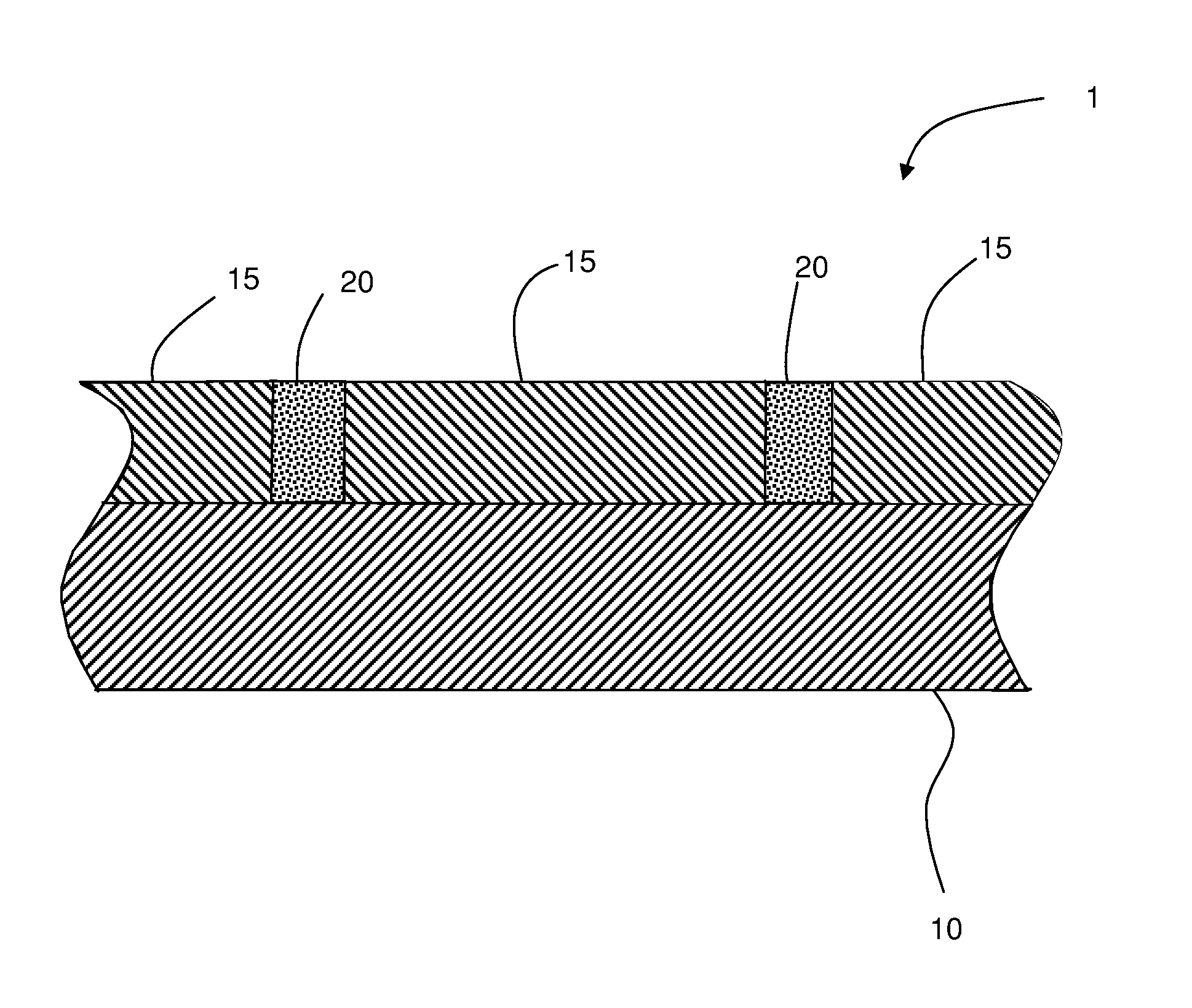
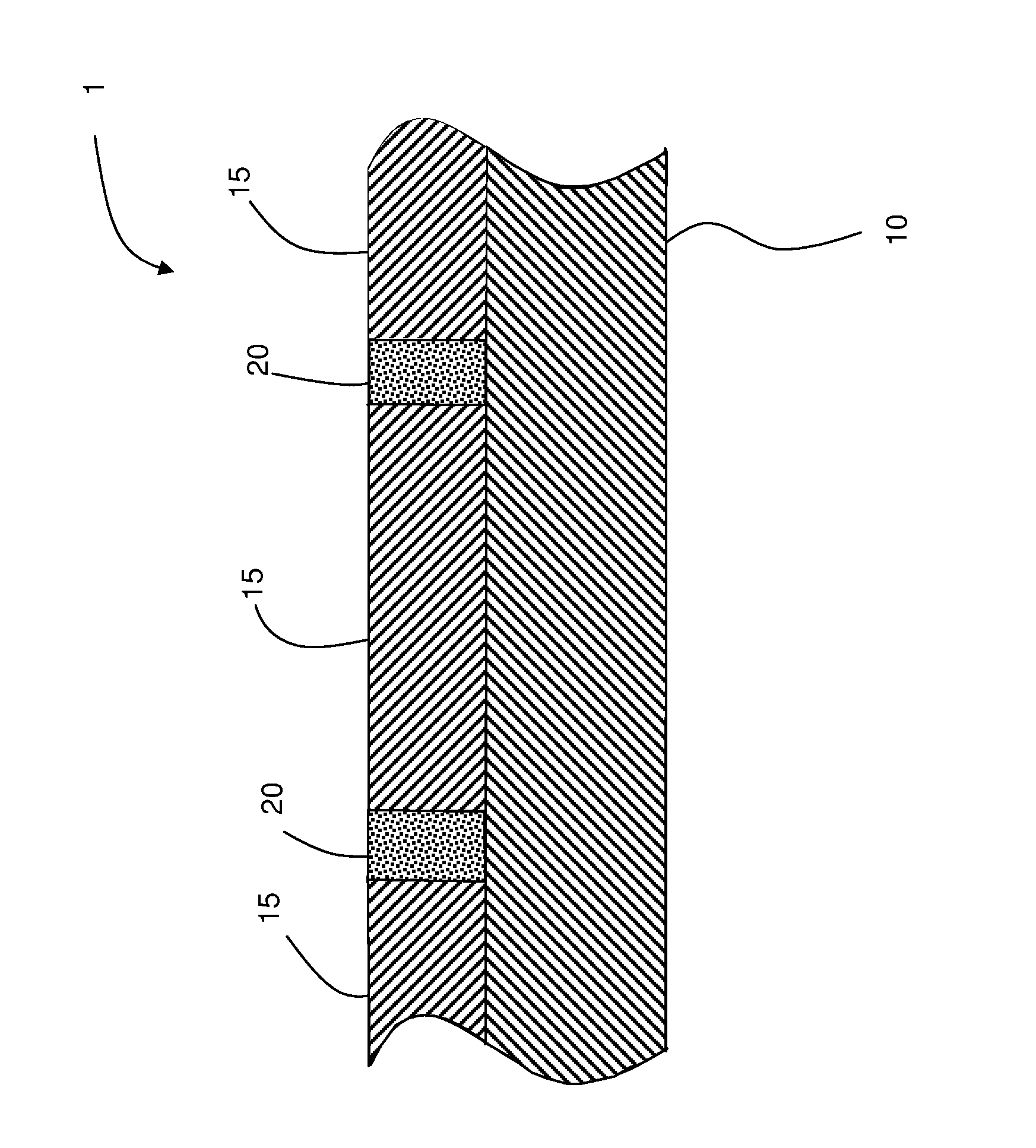
[0038]A test sample was prepared by attaching three PICA ablative tiles to a carbon-resin composite substrate with adhesive in a configuration so as to provide a T-joint shaped gap line between the three tiles. A temporary border was placed around the outside edge of the test sample in order to retain material with which the gaps would be filled, and the top surface of the PICA tiles was covered with a protective tape, and a powder composition containing 40% by weight phenolic resin, 40% carbon fibers, and 20% phenolic microballoons was poured into the gaps along the gap line. Voids in the powder fill in the gaps were manually by physical manipulation with a pick, and additional powder composition was packed into the gaps, resulting in a density of powder composition in the gaps (measured by dividing total mass of powder disposed into the gaps by the calculated gap volume) of 0.45 g / cm3. The initial total loose volume of powder composition was about 120% of the final packed volume. ...

example 2

Sample 1

[0039]A test sample was prepared by attaching a commercially-available fiberglass phenolic flexible core honeycomb material to an aluminum plate substrate with adhesive. The surface of fiberglass phenolic core was treated with a 10% solution of phenolic resin and dried. A powder composition containing 40% by weight phenolic resin, 40% carbon fibers, and 20% phenolic microballoons was poured and packed into the honeycomb cells, and the test sample was baked to cure the powder composition. The test sample was subjected to arc jet testing at Boeing Technological Services Large Core Arc Tunnel (LCAT) facility using a conventional shear specimen configuration. The results showed excellent ablative performance and cohesiveness of the cured powder composition, and generally good adhesion of the cured powder composition to the fiberglass phenolic core.

Sample 2

[0040]A second test sample was prepared by attaching a commercially-available fiberglass phenolic flexible core honeycomb mat...


PUM

PropertyMeasurementUnit
Temperatureaaaaaaaaaa
Fractionaaaaaaaaaa

Abstract

A robust, chemically, structurally, and thermodynamically compatible ablative gap filler that can be processed with ease is provided. The gap filler uses a carbon phenolic mixture that has nearly the same material property characteristics as the adjacent PICA or carbon phenolic tiles. The gap filler is applied into the gaps using an innovative processing approach that involves preparation of a ‘dry mixture’ of the ingredients, which is then packed manually or robotically (if needed) into the gaps. During the packing process, the dry mixture may be vented, and pressed periodically to ensure that there are no trapped voids. After each gap is adequately filled with the mixture, the assembly is bagged and cured in the oven at about 250 or 300° F. for about 1.5 to 2 hours. The gap filler thereby forms a bond with the adjacent PICA or carbon phenolic tiles, without degrading or modifying the properties at any of the interfaces (e.g., with the tiles, adhesives, substrate, etc.).

Description

CROSS-REFERENCES TO RELATED APPLICATIONS[0001]This patent application claims priority to U.S. Provisional Patent Application Ser. No. 61 / 152,594 filed Feb. 13, 2009, the disclosure of which is incorporated herein by reference in its entirety.STATEMENT REGARDING FEDERALLY SPONSORED RESEARCH OR DEVELOPMENT[0002]Not Applicable.BACKGROUND OF THE INVENTION[0003]The present invention generally relates to ablative heat shields for atmospheric entry or re-entry and, in particular, to carbon phenolic ablative compositions for use with such heat shields.[0004]Ablator materials (e.g., carbon phenolic-based ablators, such as phenolic impregnated carbon ablator (PICA)), are often used as the thermal protection system in the fabrication of aeroshells of space vehicle re-entry systems. Such aeroshells have been fabricated by bonding multiple tiles of these carbon phenolic ablators onto a substrate structure, and then filling the gaps between these tiles with room temperature vulcanizing type mater...

Claims


Application Information

Patent Timeline
IPC IPC(8): B32B3/10B32B3/12
CPCC09D5/34B32B5/02B32B3/14B64G1/58B32B2260/021B32B2260/046Y10T428/164B32B2307/304B32B2307/306B32B2605/00Y10T428/163Y10T428/166Y10T428/24157B32B2262/106
Inventor RAWAL, SURAJ P.WILLCOCKSON, WILLIAM H.HUND, RICHARD A.
Owner LOCKHEED MARTIN CORP
Learn More