RTP heating system and method

a technology of rapid temperature process and heating method, which is applied in the direction of drying, drying machines, lighting and heating apparatus, etc., can solve the problems of difficult integration so far, and achieve the effect of less direct heating

Inactive Publication Date: 2013-02-12
ADPV TECH
View PDF7 Cites 2 Cited by
  • Summary
  • Abstract
  • Description
  • Claims
  • Application Information

AI Technical Summary

Benefits of technology

[0010]The primary objective of the present invention is to provide an RTP heating system, which can apply heating of different temperatures to the upper and lower surfaces of the photovoltaic devices having the glass substrate to allow the upper surface to meet the requirement for manufacturing temperature of the light absorption layer and to prevent the heat of the lower surface from softening and deforming the glass substrate in such a way that the light absorption layer can be manufactured on the glass substrate.
[0011]The secondary objective of the present invention is to provide an RTP heating method, which can manufacture the light absorption layer on the glass substrate without softening and deforming the glass substrate.
[0013]The foregoing objectives of the present invention are attained by the RTP heating method, which is to heat a photovoltaic-device intermediate product having a glass substrate and a Mo layer coated onto the glass substrate. The RTP heating method includes the steps of placing the photovoltaic-device intermediate product on a support member, then heating an upper surface of the photovoltaic-device intermediate product by a heating element, and finally heating a lower surface of the photovoltaic-device intermediate product through the support member. The heating element can emit infrared rays, each of which is limited to a predetermined wavelength, to heat the upper surface of the photovoltaic-device intermediate product in such a way that most of the heat is reflected by the Mo layer to apply less direct heating to the glass substrate and to apply more direct heating to the light absorption layer. In this way, the heating degree can be controlled to make the temperature of the upper surface of the photovoltaic-device intermediate product be higher than deformation temperature of the glass substrate and to make the temperature of the lower surface of the photovoltaic-device intermediate product be lower than the deformation temperature of the glass substrate. Besides, the upper and lower surfaces of the photovoltaic-device intermediate product can be heated under different temperatures separately to prevent the glass substrate below the photovoltaic-device intermediate product from softening and deformation and to allow production of the light absorption layer on the Mo layer.

Problems solved by technology

When the light absorption layer is manufactured by the RTP, if the substrate is made of glass, there will be a problem.
As can be seen from the above, in the existing temperature control technology, it is very difficult so far to integrate the manufacturing temperature (500° C. and higher) of the light absorption layer and the deformation temperature (510° C.) of the glass on the glass substrate to allow the light absorption layer to be manufactured on the glass.

Method used


Image

  • RTP heating system and method
  • RTP heating system and method
  • RTP heating system and method

Examples


second embodiment

[0030]The heating method of the second embodiment takes advantages of the characteristic that the Mo layer 54 can reflect the infrared rays to isolate and prevent most of the infrared rays from directly heating the glass substrate 52 to further heat the upper and lower surfaces of the photovoltaic-device intermediate product 51 separately.

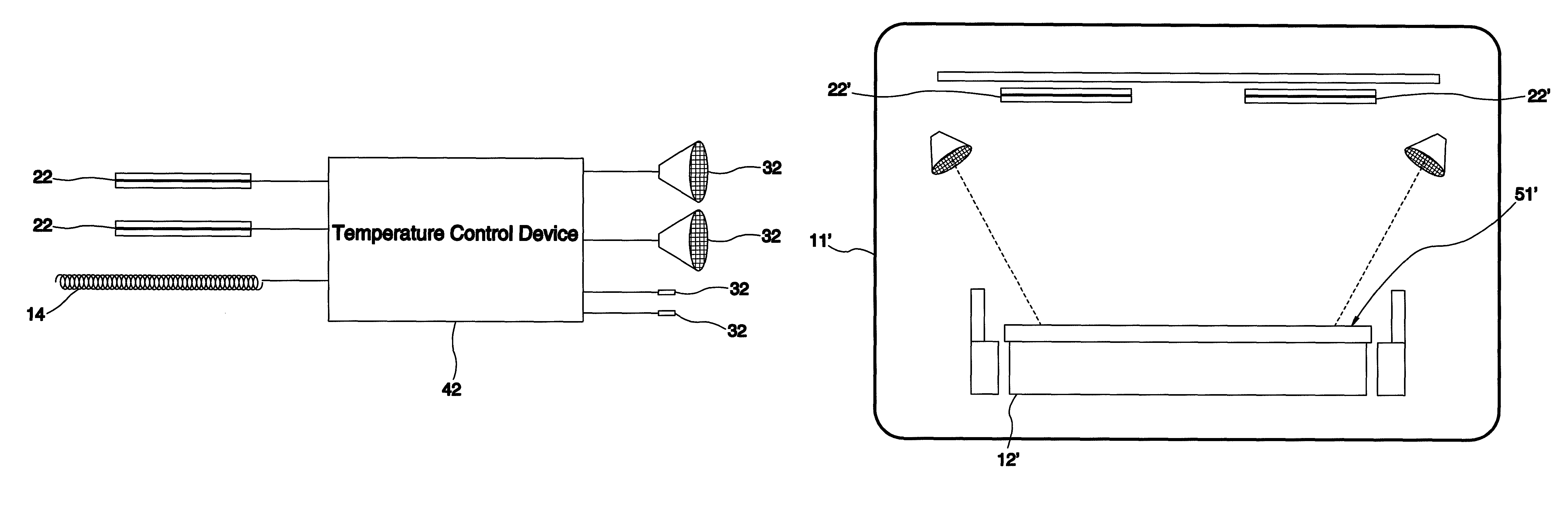
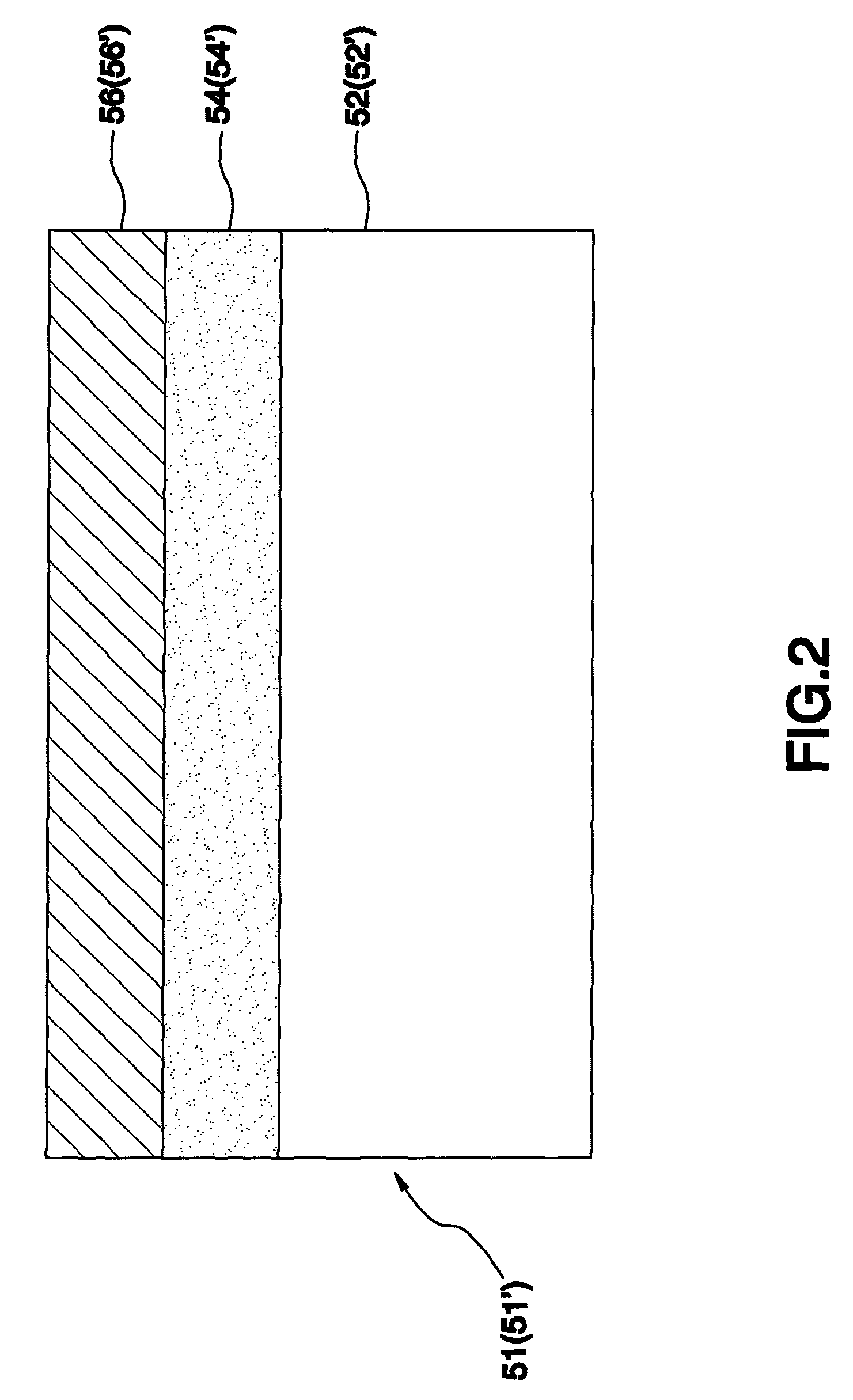
[0031]Referring to FIG. 2 in view of FIG. 4, an RTP heating method in accordance with a third preferred embodiment of the present invention is to heat a photovoltaic-device intermediate product 51′ having a glass substrate 52′, a Mo layer 54′ coated on the glass subset 52′, and a light absorption layer 56′ in formation includes the following steps.

[0032]a) Preheat the photovoltaic-device intermediate product 51′ externally and then send it into the chamber 11′ under the condition that the photovoltaic-device intermediate product 51′ remains a predetermined temperature, 425° C. in this embodiment. Alternatively, the photovoltaic-device intermediate ...

third embodiment

[0035]In the third embodiment, in the step c), the upper surface of the photovoltaic-device intermediate product 51′ is heated up to 500° C. and higher and the lower surface of the photovoltaic-device intermediate product 51′ is thermally dissipated down to 500° C. and lower.

[0036]The heating method of the third embodiment takes advantages of the characteristic that the Mo layer 54 can reflect the infrared rays to isolate and prevent most of the infrared rays from directly heating the glass substrate 52 to further heat the upper surface of the photovoltaic-device intermediate product 51′ other than the lower surface directly. Besides, the heat of the lower surface can be dissipated through the support member, such that it will not happen that the glass substrate 52′ is softened and deformed.

[0037]In conclusion, the present invention includes the following advantages and effects.

[0038]1. The heating of different temperatures can be applied to the upper and lower surfaces of the photo...


PUM


Abstract

An RTP heating system and an RTP heating method, which can heat a photovoltaic-device intermediate product having a glass substrate, a Mo layer, and a light absorption layer in formation. The RTP heating system is composed of a chamber; a support member located in the chamber; a heating element mounted in the chamber for emitting infrared rays for heating; and a plurality of temperature sensors and a temperature control device for sensing and controlling thermal sources from the heating element and the support member. The infrared rays can be mostly reflected off the Mo layer to apply less direct heating to the glass substrate. Accordingly, the upper and lower surfaces of the photovoltaic-device intermediate product can be heated under different temperatures separately to prevent the glass substrate below the photovoltaic-device intermediate product from softening and deformation and to allow production of the light absorption layer on the Mo layer.

Description

BACKGROUND OF THE INVENTION[0001]1. Field of the Invention[0002]The present invention relates generally to manufacturing technology of photovoltaic devices, and more particularly, to a rapid temperature process (RTP) heating system and an RTP heating method.[0003]2. Description of the Related Art[0004]The existing photovoltaic devices are usually made by that a Mo layer is disposed on a glass substrate and a light absorption layer, e.g. copper indium gallium selenide (CIGS) layer or copper indium selenide (CIS) layer, is produced on the Mo layer. When it is intended to produce the light absorption layer, the temperature needs to be heightened up to 500° C. and higher, and then the light absorption layer can be formed on the Mo layer by sputtering, vapor deposition, electroplating, or inkjet.[0005]In the process of production of the above-mentioned light absorption layer, the method of heightening the temperature includes the popular RTP is to heat photovoltaic devices by a thermal s...

Claims


Application Information

Patent Timeline
Patent Type & Authority Patents(United States)
IPC IPC(8): H01L31/18
CPCH01L31/18
Inventor HUANG, SHIEZEN STEVEN
Owner ADPV TECH
Why Eureka
Try Eureka