Dynamically controllable drive circuit for parallel array of light emitting diodes

a technology of driving circuit and light-emitting diodes, which is applied in the direction of process and machine control, instruments, pulse techniques, etc., can solve problems such as polarity reverse, and achieve accurate matching, reduce circuitry variability, and reduce the effect of drive current variations

Active Publication Date: 2013-02-12
BCD SHANGHAI MICRO ELECTRONICS CO LTD
View PDF5 Cites 10 Cited by
  • Summary
  • Abstract
  • Description
  • Claims
  • Application Information

AI Technical Summary

Benefits of technology

[0011]The present invention overcomes the aforementioned drawbacks by providing a parallel LED drive circuit that reduces variations between drive currents for all LEDs by reducing circuitry variability, such that the drive currents for all LEDs is substantially determined by a sampling resistor, which can be accurately matched throughout the drive circuit. More particularly, the present invention provides a system and method whereby the polarity of an input offset voltage of a chopper operational amplifier used to control the drive circuits can be reversed using a switching control signal to substantially reduce affects of the input offset voltage.

Problems solved by technology

The input transistor pair and current mirror transistor pair are mismatched, such that when the switching control signal is switched between a first state and a second state, electrical positions of the input transistor pair switch and electrical positions of the current mirror transistor pair switch to thereby cause a reversing of polarity of the input offset voltage of the chopper operational amplifier.

Method used


Image

  • Dynamically controllable drive circuit for parallel array of light emitting diodes
  • Dynamically controllable drive circuit for parallel array of light emitting diodes
  • Dynamically controllable drive circuit for parallel array of light emitting diodes

Examples


Embodiment Construction

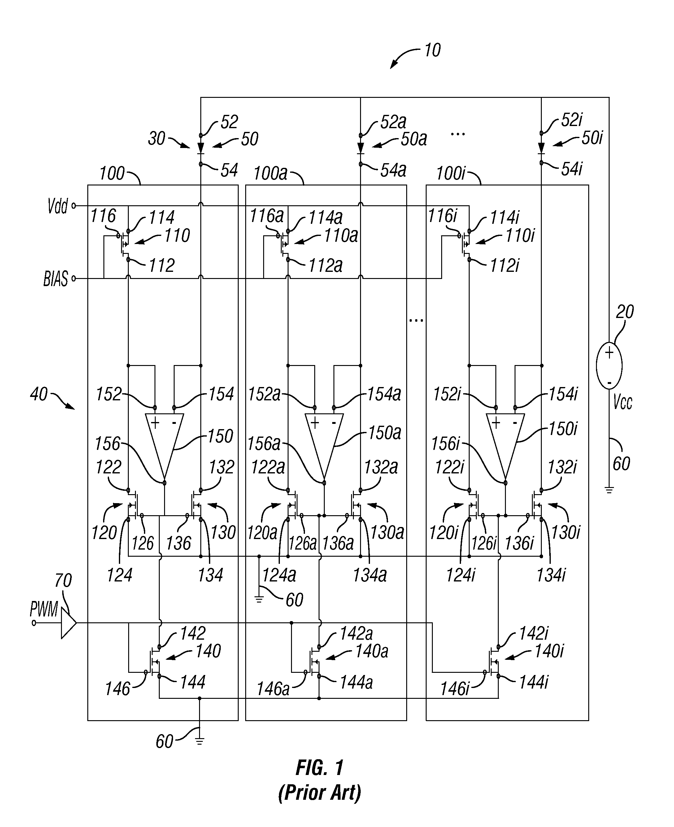
[0019]FIG. 1 is a circuit diagram showing a light emitting diode (LED) lighting system 10 including a power source 20, an array of LEDs 30, and a drive circuit 40. The array of LEDs 30 includes a plurality of LEDs 50, 50a, 50i, each having respective anodes 52, 52a, 52i and cathodes 54, 54a, 54i. Though, for exemplary purposes, the array of LEDs 30 is shown with three LEDs 50, 50a, 50i, any number of LEDs may be included in the array of LEDs 30. Furthermore, the notation of “i” is intended to indicate the “ith” component and is not representative of an array containing components “a” through “i”.

[0020]Each LED 50, 50a, 50i is coupled to the power source 20 through the anode 52, 52a, 52i to receive a drive current (ILED). Also, each LED 50, 50a, 50i is coupled to the drive circuit 40 through the cathode 54, 54a, 54i. More particularly, each LED 50, 50a, 50i is coupled to a respective drive module 100, 100a, 100i of the drive circuit 40. Since all drive modules 100, 100a, 100i have su...


PUM


Abstract

The present invention relates to a parallel light emitting diode (“LED”) drive circuit and provides a drive circuit configured to drive a parallel array of LEDs. The drive circuit comprises: a switching control signal generator, a plurality of switches, a plurality of sampling resistors, and a plurality of chopper amplifiers. Each switch is coupled to a respective LED in the LED array. Each chopper operational amplifier configured to receive a reference voltage and a switching control signal generated by the switching control signal generator and generate an input offset voltage. Each chopper operational amplifier includes a differential amplifier including an input transistor pair and a current mirror transistor pair, of which the electrical positions can be reserved when the switching control signal is switched between a first state and a second state, wherein the offset voltage, which causes the lightness mismatching in a parallel LED circuit, can be cancelled.

Description

CROSS-REFERENCE TO RELATED APPLICATIONS[0001]This application claims the benefit of Chinese utility model patent applications Serial No. 201020128193.6 filed on Mar. 8, 2010 and entitled “A Parallel Light Emitting Diode (LED) Drive Circuit” and Serial No. 201020128299.6 filed on Mar. 8, 2010 and entitled “A Parallel Lighting Emitting Diode (LED) Drive Circuit”, which are incorporated herein be reference.FIELD OF THE INVENTION[0002]The present invention generally relates to a drive circuit for a parallel array of light emitting diodes (LEDs).BACKGROUND OF THE INVENTION[0003]Light-Emitting Diodes (“LEDs”) are semiconductor light sources. With the development of high efficiency and high power LEDs, LEDs have been widely used for lighting and illumination sources. While monochrome displays can use colored light sources, such as electroluminescent back lights or colored LEDs, color displays still require a white LED as a light source to properly display color.[0004]Using LEDs for illumin...

Claims


Application Information

Patent Timeline
Patent Type & Authority Patents(United States)
IPC IPC(8): H05B37/02H05B44/00
CPCH05B33/0818H05B33/0827H05B33/0845H05B45/46H05B45/37H05B45/10
Inventor LIU, ZUTAOCHENG, KUNSUN, JIANBOSHI, GANG
Owner BCD SHANGHAI MICRO ELECTRONICS CO LTD
Why Eureka
Try Eureka