Frequency offset monitoring device and optical coherent receiver

a frequency offset monitoring and optical coherent receiver technology, applied in the field of optical coherent receivers, can solve the problems of difficult implementation of devices in optical communication systems, difficult high speed dsp, and difficult current electrical technology, so as to reduce the demand on the operation speed, avoid zero offset of detected signals, and reduce the demand on electric devices used in frequency offset monitoring according to the fifth aspect of the present invention.

Active Publication Date: 2013-02-12
FUJITSU LTD
View PDF19 Cites 17 Cited by
  • Summary
  • Abstract
  • Description
  • Claims
  • Application Information

AI Technical Summary

Benefits of technology

[0014]In order to solve these problems, the present invention provides a low speed analog approach and a simplified digital approach which relax the strict hardware requirement of speed. This is very important for the high capacity optical communication system.
[0021]According to the first to fourth aspects of the present invention, the first low-pass filter and the second low-pass filter reduce the device speed of the first multiplier, the second multiplier, the first delayer, the second delayer and the subtracter from the full band to the bandwidth of the low-pass filters. At the same time, the monitoring range is also reduced to the bandwidth of the first low-pass filter and the second low-pass filter.
[0032]According to the fifth aspect to the thirteenth aspect of the present invention, since the speed of the signals converted by the first and second serial-to-parallel converters is N times lower than the full band signal s(t), demand on the electric devices used in the frequency offset monitoring is greatly reduced, thereby solving the speed problem in the prior art as discussed above.
[0033]In addition, demand on the electric devices used in the frequency offset monitoring according to the fifth aspect of the present invention can be further reduced. In the seventh aspect of the present invention, a digital down-sampler is inserted between the first and second serial-to-parallel converters and the frequency offset monitor of the low speed frequency offset monitoring device according to the present invention, so as to further reduce the demand on the operational speed of the frequency offset monitoring.

Problems solved by technology

A very important issue in a coherent receiver is how to recover the carrier phase.
It is common in electrical communication, but such device is very difficult for implementation in the optical communication system, since the bandwidth of an electric signal in optical communication is in the scale of ˜10 GHz.
Such a high speed DSP is currently very difficult.
Such ˜10 GHz high speed device is difficult for the current electrical technology.
Anyway, such large frequency offset is disadvantageous to the coherent system, even in the case of using the phase locked loop.

Method used


Image

  • Frequency offset monitoring device and optical coherent receiver
  • Frequency offset monitoring device and optical coherent receiver
  • Frequency offset monitoring device and optical coherent receiver

Examples


Embodiment Construction

[0054]The main purpose of the present invention is to overcome the speed problem in the aforementioned prior art. Embodiments of the present invention will be described in detail below with reference to the accompanying drawings.

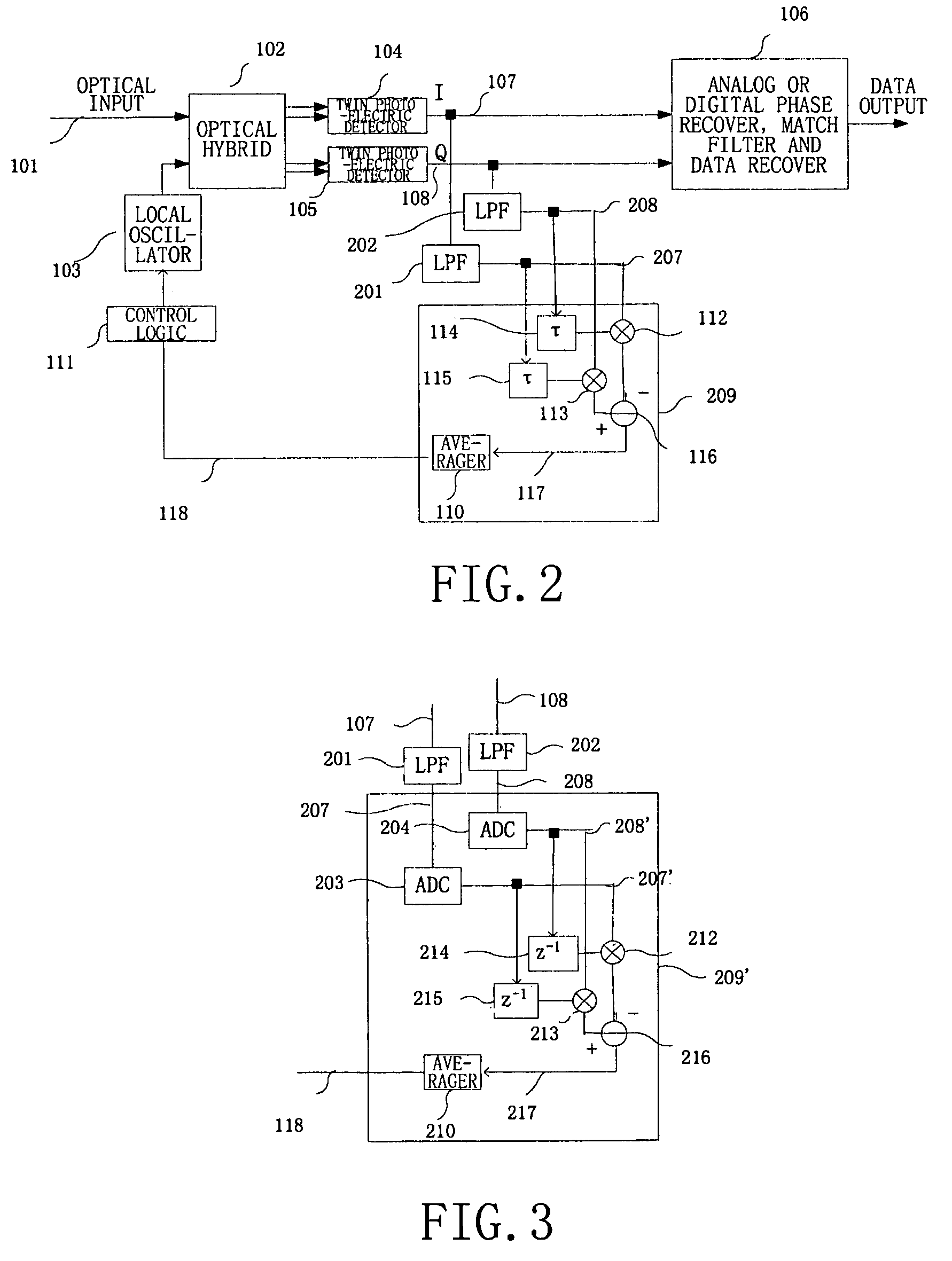
[0055]FIG. 2 shows an optical coherent receiver with analog cross product automatic frequency control according to the present invention achievable by a low speed circuit.

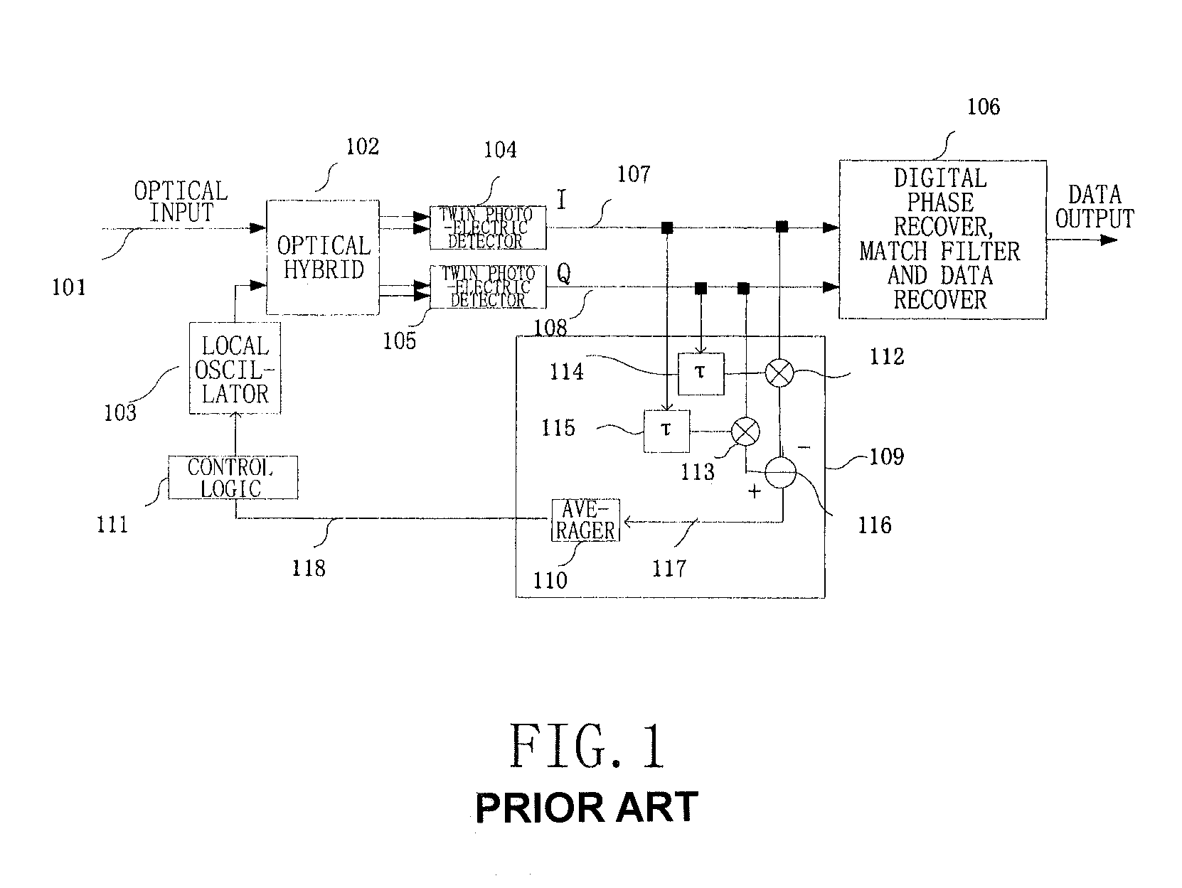
[0056]The optical coherent receiver as shown in FIG. 2 is similar in structure to that shown in FIG. 1, and the same reference numerals used in FIG. 1 are used in FIG. 2 to indicate identical or similar component parts. Besides the component parts of the structure shown in FIG. 1, in FIG. 2, there are added two low-pass filters (LPF), namely a first low-pass filter 201 and a second low pass filter 202, and the frequency offset monitor 209 calculates the self-correlation of low pass filtered signals 207 and 208, instead of the full band signals (namely the cophase signal I 107 and the quadra...


PUM


Abstract

The present invention provides a frequency offset monitoring device and an optical coherent receiver. A low speed frequency offset monitoring device comprises a signal speed lowering section, for lowering the speed of an inputted signal and outputting the speed lowered signal, and a frequency offset monitor, for monitoring frequency offset of the speed lowered signal outputted by the signal speed lowering section.

Description

TECHNICAL FIELD OF THE INVENTION[0001]The present invention generally relates to an optical coherent receiver in an optical communication system, and more particularly to an apparatus and a method for automatic frequency control in the optical coherent receiver.BACKGROUND OF THE INVENTION[0002]With the increasing demand on capacity and system flexibility, optical coherent technology has again attracted more-and more attention. In comparison with incoherent technology, such as direct detection of On-Off keying (OOK), and delayed detection, namely self-coherent technology of differential phase shift keying (DPSK), the coherent technology has the following advantages: it has approximately 3 dB optical signal to noise ratio (OSNR) benefit as compared with differential detection; it can use equalization technology to countermeasure linear distortion in optical domain; and it can deal with advanced modulation schemes such as quadrature amplitude modulation (QAM).[0003]A very important iss...

Claims


Application Information

Patent Timeline
Patent Type & Authority Patents(United States)
IPC IPC(8): H04B10/60H04B10/516H04B10/00H04B10/61
CPCH04B10/61H04B10/613H04B10/6164H04B10/63
Inventor TAO, ZHENNINGZHANG, HUIJIANHOSHIDA, TAKESHILI, LEI
Owner FUJITSU LTD
Why Eureka
Try Eureka