Delay line structure

a delay line and spiral technology, applied in the direction of waveguides, electrical apparatus construction details, waveguide type devices, etc., can solve problems such as crosstalk noise disturbance, achieve the effect of effectively reducing noise disturbance, enhancing synchronized transmission of signals, and enhancing transmission speed

Inactive Publication Date: 2013-02-19
CHUNG YUAN CHRISTIAN UNIVERSITY
View PDF4 Cites 29 Cited by
  • Summary
  • Abstract
  • Description
  • Claims
  • Application Information

AI Technical Summary

Benefits of technology

[0009]In the prior art technique, crosstalk noise disturbance is common at the straight sections of the spiral delay lines and there exists the different transmission speed of the signals at the bent section. The main object of the present invention is to provide a differential flat spiral line structure with grounding guard traces, wherein a width at the bent section between the spiral delay lines is reduce so as to form strong coupling effects, thereby effectively lowering noise disturbance and crosstalk effects.
[0010]The other object of the present invention is to provide a differential flat spiral delay line structure, wherein distances between the spiral delay lines consisting of the bent sections, which unequal lengths are reduced, thereby signal synchronizing for transmission the signals at the same rate.
[0022]Concerning easy generating of crosstalk noise disturbance at the straight section and different transmission speed at the bent section of the spiral delay line in the prior art, the flat spiral delay line structure of the present invention is provided with the grounding guard trace. The present invention effectively reduces the noise disturbance, thereby enhancing the synchronize transmission of the signal due the reasons that each of the spiral delay lines has at the bent section (consisting of the first outer bent section, the second outer bent section and the inner bent parts) a width smaller the straight section (consisting of the first outer straight section, the second outer straight section and the inner straight parts).
[0023]In addition, since the width of each of the spiral delay lines is small at the bent sections when compared to the prior art ones, the difference in transmission speed is effectively reduced due to the digital signal synchronizing.

Problems solved by technology

In the prior art technique, crosstalk noise disturbance is common at the straight sections of the spiral delay lines and there exists the different transmission speed of the signals at the bent section.

Method used


Image

  • Delay line structure
  • Delay line structure
  • Delay line structure

Examples


Embodiment Construction

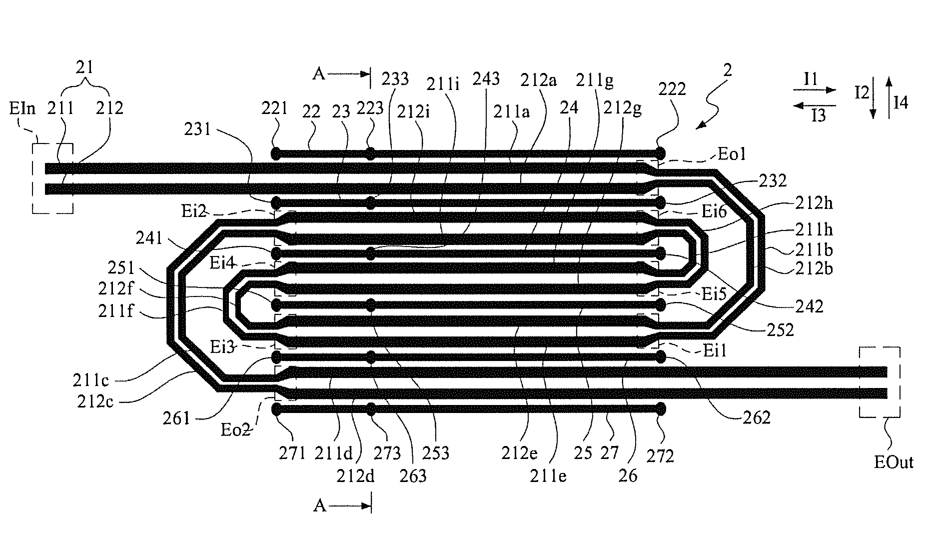
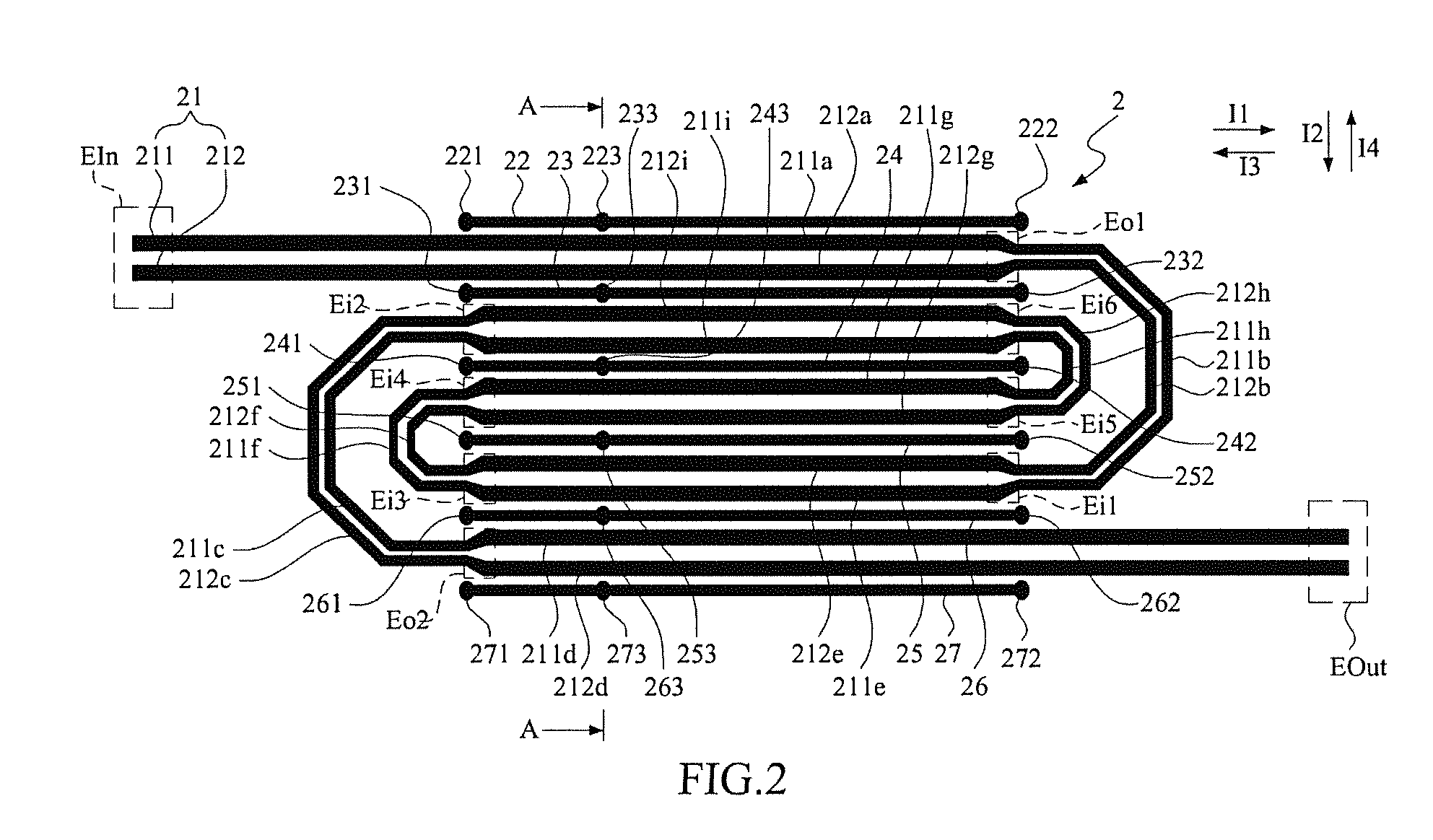
[0033]The present invention relates to a differential flat spiral delay line structure, which is widely implemented in various circuit systems for increasing a delay time in order to signal synchronizing so that the signals can be transmitted at the same time. In the following description, an embodiment is illustrated to provide a thorough understanding of the present invention, where two microstrip lines or two strip lines are used for two spiral delay lines. It will be appreciated by one skilled in the art that variations of these specific details are possible while still achieving the results of the present invention.

[0034]Referring to FIG. 2 and FIG. 3, wherein FIG. 2 illustrates an embodiment of a differential flat spiral delay line structure of the present invention disposed on a substrate while FIG. 3 illustrates a cross-sectional view of the differential flat spiral delay line structure of the present invention taken along the lines A-A in FIG. 2 when two spiral delay lines ...


PUM


Abstract

A delay line structure disposed on a substrate having a dielectric base layer formed with a via, a layout layer and a grounding layer with a grounding circuit, includes two parallel spiral delay lines having a first outer straight section, a first outer bent section, an inner spiral region, a second outer bent section and a second outer straight section. The inner spiral region bends reciprocally between the first and second outer straight sections to form several inner bent parts and several inner straight parts. A grounding guard trace is disposed among the first and second outer straight sections and the inner straight parts and is coupled electrically to the grounding circuit, wherein each of the first and second outer bent sections and the inner bent parts has a width smaller than each of the first and second outer straight sections and the inner straight parts.

Description

[0001]This application claims the benefits of the Taiwan Patent Application Serial No. 100128341 filed on Aug. 9, 2011, the subject matter of which is incorporated herein by reference.BACKGROUND OF THE INVENTION[0002]1. Field of the Invention[0003]The present invention relates to a differential flat spiral delay line structure, and more particularly to a differential flat spiral delay line structure with grounding guard traces and strong coupling line parts.[0004]2. Description of the Prior Art[0005]Signal synchronizing is always a concern when it comes to the high speed digital signal. Usually the requirement of synchronizing signals is met by increasing the delay time with a delay line. To be more specific, for high speed signal or signal over shorter transmission circuit, a delay line structure is usually used in order to delay the transmission time.[0006]Due to limited space in the substrate of an electronic device, the delay line is usually bent in order save the occupying spac...

Claims


Application Information

Patent Timeline
Patent Type & Authority Patents(United States)
IPC IPC(8): H05K1/00
CPCH05K1/0245H05K1/0248H05K1/025H05K2201/09727H05K2201/09263H05K1/0219
Inventor SHIUE, GUANG-HWASHIU, JIA-HUNG
Owner CHUNG YUAN CHRISTIAN UNIVERSITY
Why Eureka
Try Eureka