
Adaptive re-use of waste insulated glass window units as thermal solar energy collection panels

a technology of solar energy collection and waste insulated glass, which is applied in the direction of heat collector mounting/support, applications, lighting and heating apparatus, etc., can solve the problems of igus being limited to a useful lifespan of approximately twenty years, affecting the thermal insulation of the glass pane, so as to prevent freezing damage, improve the conductivity of the plastic tube material, and increase the length

Inactive Publication Date: 2013-02-26
MILLS GREGORY B
View PDF29 Cites 4 Cited by
  • Summary
  • Abstract
  • Description
  • Claims
  • Application Information

AI Technical Summary

Benefits of technology

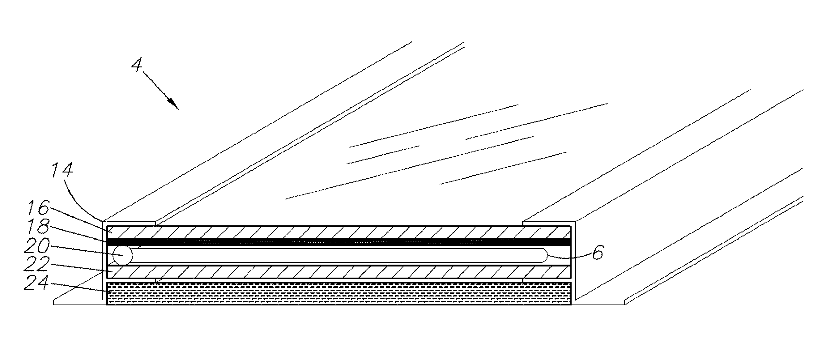
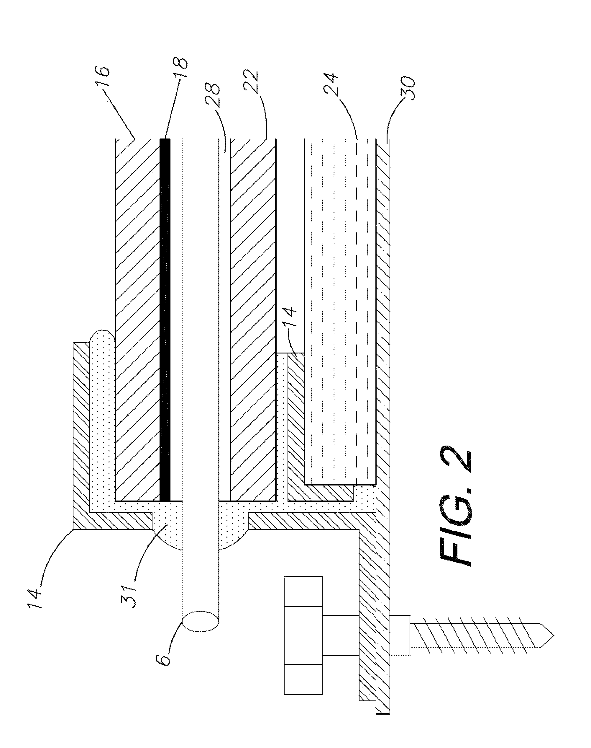
This invention describes a new way to fill the gap between the glass panes of an old IGU (insulating glass unit) with a fluid containing carbon particles or a low-technology, inexpensive collector plate. The fluid or inexpensive material directly absorbs the heat energy at the solar panel and transmits the collected energy when circulated back to a heat exchanger in conductive contact with the product water. This approach replaces the commonly costly copper plate or foil with a black fluid or inexpensive material that works well with high-temperature extruded plastic tubing. The added soft tubing length also offers a large compressible mass within the gap between the glass elements to prevent freezing damage. This invention allows for efficient energy conversion and utilization while also providing a cost-effective alternative to traditional methods.

Problems solved by technology

Conditioning of air with fossil energy, whether the air is heated or cooled, can be wasted through contact with highly thermally conductive glass doors and windows.
IGUs are limited to a useful lifespan of approximately twenty years.
Humidity within the space between the glass panes can build up, causing water to condense on the inner glass surfaces.
The trapped humid air eventually creates a fog which condenses on the sealed interior glass surfaces.
This creates an unsightly foggy deposit that is quite visible, unattractive, and nearly impossible and extremely uneconomical to clean and correct.
Additional wasted IGUs are a result of updating structures with newer, more efficient thermal window units.
Although it is theoretically possible to disassemble the thermal window, remove the rubber gasket, separate and clean the glass panes and reform the IGU with fresh gasket materials, such efforts are laborious and mechanically difficult and thus economically ineffective.
It is difficult to adequately clean the interior glass surfaces, (which develops a well attached lime like deposit) install a fresh, functional gasket, re-introduce inert gas between the panes, while at the same time fully remove potentially humid air.
Without the proper working conditions and equipment, this becomes an impractical exercise.
Even when IGUs are disassembled and cleaned, such cleaning procedures are not always successful and the deterioration of the gasket is generally not addressed by cleaning procedures.
The result is that many spoiled IGUs with fog and / or lime deposits on the interior surfaces between the panes of glass are normally wasted and replaced with new IGUs.
Even recycling the used glass in old IGUs by melting them down is frustrated due to contamination of such glass by the well attached rubber gasket, which is very hard to fully remove and the “E” coatings on the glass are also considered contaminants.
Bits of rubber gasket contamination in a large batch of molten glass spoils the entire batch for most uses.
Discarding used glass units also wastes the energy it takes to replace them.
Even melting used glass down and re-using it as molten glass only saves about 50% of the energy required to cast new glass and is problematic as stated above.
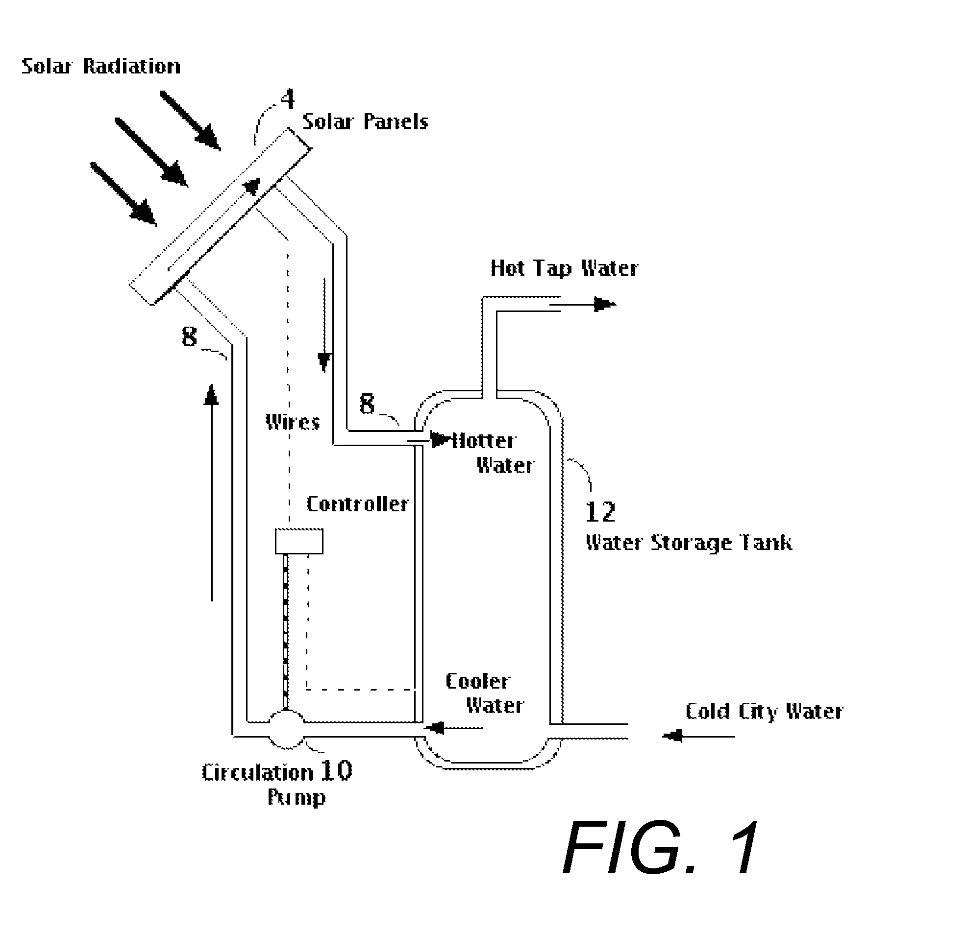
Hotter water from the solar array tends to rise to the top of the storage tank and cooler water tends to sink to the bottom of the storage tank.
However, any transfer of heat across a heat exchanger will slightly lower the efficiency of the system, and this loss of efficiency must be taken into account.
Anti-freeze as the heat absorption fluid protects the panels from damage in freezing weather but slightly reduces the effectiveness of plain water.

Method used


Image

  • Adaptive re-use of waste insulated glass window units as thermal solar energy collection panels
  • Adaptive re-use of waste insulated glass window units as thermal solar energy collection panels
  • Adaptive re-use of waste insulated glass window units as thermal solar energy collection panels

Examples


Embodiment Construction

I. Introduction and Environment

[0025]As required, detailed aspects of the disclosed subject matter are disclosed herein; however, it is to be understood that the disclosed aspects are merely exemplary of the invention, which may be embodied in various forms. Therefore, specific structural and functional details disclosed herein are not to be interpreted as limiting, but merely as a basis for the claims and as a representative basis for teaching one skilled in the art how to variously employ the present invention in virtually any appropriately detailed structure.

[0026]Certain terminology will be used in the following description for convenience in reference only and will not be limiting. For example, up, down, front, back, right and left refer to the invention as orientated in the view being referred to. The words, “inwardly” and “outwardly” refer to directions toward and away from, respectively, the geometric center of the aspect being described and designated parts thereof. Said te...


PUM

PropertyMeasurementUnit
perimeteraaaaaaaaaa
temperatureaaaaaaaaaa
solar radiation-absorbingaaaaaaaaaa

Abstract

A method of repurposing dual-paned insulated glass window units (IGUs) that would otherwise be put to waste into thermal solar panels capable of generating hot water for a residence or other structure. The method includes the steps of removing an existing IGU, disassembling and cleaning the IGU, and reassembling the IGU with a new silicon seal and fluid channels for connection to a looped solar heating system. The space between the panes may be filled with a liquid to be heated by solar radiation, or alternatively by a conduit which transports the liquid through the panel.

Description

CROSS REFERENCE TO RELATED APPLICATION[0001]This application claims priority in provisional application No. 61 / 204,338, filed Jan. 5, 2009, which is incorporated herein by reference.BACKGROUND OF THE INVENTION[0002]1. Field of the Invention[0003]The present invention relates generally to a method of adapting and repurposing used, spoiled, or excess thermal window glass units that would normally go to waste, into inexpensive new thermal solar energy collecting panels for the purpose of generating product hot water or for other heating or energy generation purposes.[0004]2. Description of the Related Art[0005]Thermally insulated dual pane windows have been used in new construction and remodeling for some years now. Typically, building codes mandate the use of such windows to reduce energy loss from homes and other buildings. Conditioning of air with fossil energy, whether the air is heated or cooled, can be wasted through contact with highly thermally conductive glass doors and window...

Claims


Application Information

Patent Timeline
Patent Type & Authority Patents(United States)
IPC IPC(8): E06B3/26
CPCF24J2/465F24J2/485F24J2/5211Y10T29/49716Y10T29/49815Y10T29/49355Y10T29/49353Y02E10/47F24S25/20F24S70/225F24S80/70
Inventor MILLS, GREGORY B.
Owner MILLS GREGORY B
Learn More