
Active optical element, method of producing the same

a technology of optical elements and optical elements, applied in resistor housings/enclosements/embeddings, instruments, organic dyes, etc., can solve the problems of low contrast levels, slow reaction time, low viewing angles

Inactive Publication Date: 2013-02-26
VISITRET DISPLAY OU
View PDF10 Cites 3 Cited by
  • Summary
  • Abstract
  • Description
  • Claims
  • Application Information

AI Technical Summary

Benefits of technology

The solution achieves high contrast, low energy consumption, and long image retention with intrinsic stability, enabling the production of high-resolution displays and surfaces that can change color efficiently, suitable for various applications including electronics and indicators.

Problems solved by technology

The main weaknesses of passive displays compared to active displays are: low contrast levels, low viewing angles and slow reaction times; the main strength of these displays is lower energy consumption.
The main weaknesses of active displays are that the light intensity is quite low and the image is not so visible in conditions of intensive external light (for example in direct sunlight); also their production cost and energy consumption is relatively high which limits their implementation possibilities.
With using coils it is not possible to get dots very small and the mechanical inertness of the device is very high.
This limits significantly the implementation areas of these kind of displays.
The main weaknesses of these solutions are that a high voltage is needed and their minimum physical size means that they are impossible to use in smaller high resolution displays.
A weakness of this solution is that the particles are polarized and coloured inside the paper display, during the process of composing the image, that makes the realization of the solution very complicated.

Method used


Image

  • Active optical element, method of producing the same
  • Active optical element, method of producing the same

Examples


embodiment 2

[0029]Creating the electret emulsion should be a continuous production process.[0030] Method 2 of Producing Active Element Based on the Present Invention

[0031]In this embodiment instead of polymerization of liquid monomer easily melting electrets are used (for example waxes) to get an active element. Electrets used will be emulsified in melted condition in carrier liquid (in neutral liquid, for example in fluorine carbon).

[0032]The emulsion created is subjected to a high electric field at high temperature and is chilled in it (for example in a thin pipe where the mixture flows) so the particles will acquire an electric charge.

embodiment 3

[0033]The particles with electric charge are subjected to a high UV radiance in a transparent pipe and polarizing electricity field that causes their one pole to change colour.[0034] Method 3 of Producing Active Element Based on the Present Invention

[0035]This embodiment creates an electret material double layer film that has sides with different colours as an alternative way to get an active element. The film is heated in transverse high direct current electricity field and chilled in temperature where the material of the film will acquire stabile polarization crossways to the surface. One side of the resultant film will be with one polarization and the other has opposite polarization. The film will be cut into very small pieces; to create spherical particles the pieces are burnished in a ball mill or soft moulded; the pieces will be mixed to a liquid environment with same density using suitable emulsifiers if needed.

embodiment 4

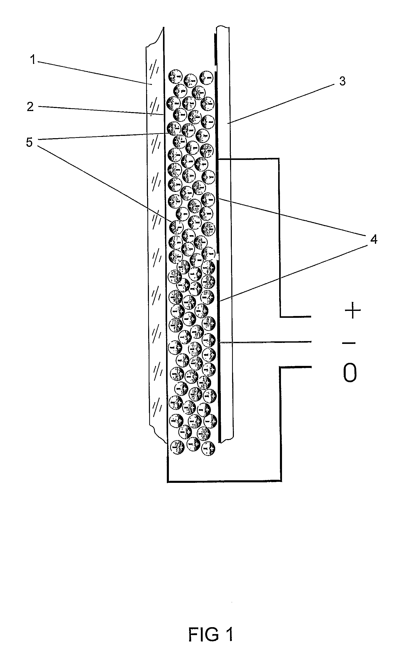
[0036]An active element that is created according to the methods in present invention is based on electret emulsion wherein it contains pre-polarised and pre-coloured micro particles of electret material in neutral liquid as emulsion and each electric pole of the particles used has a different colour.[0037] Usage of the Active Element, Based on the Present Invention, in Matrix Displays of Electronics Equipment and Surfaces and Surface Coatings that Change Colour

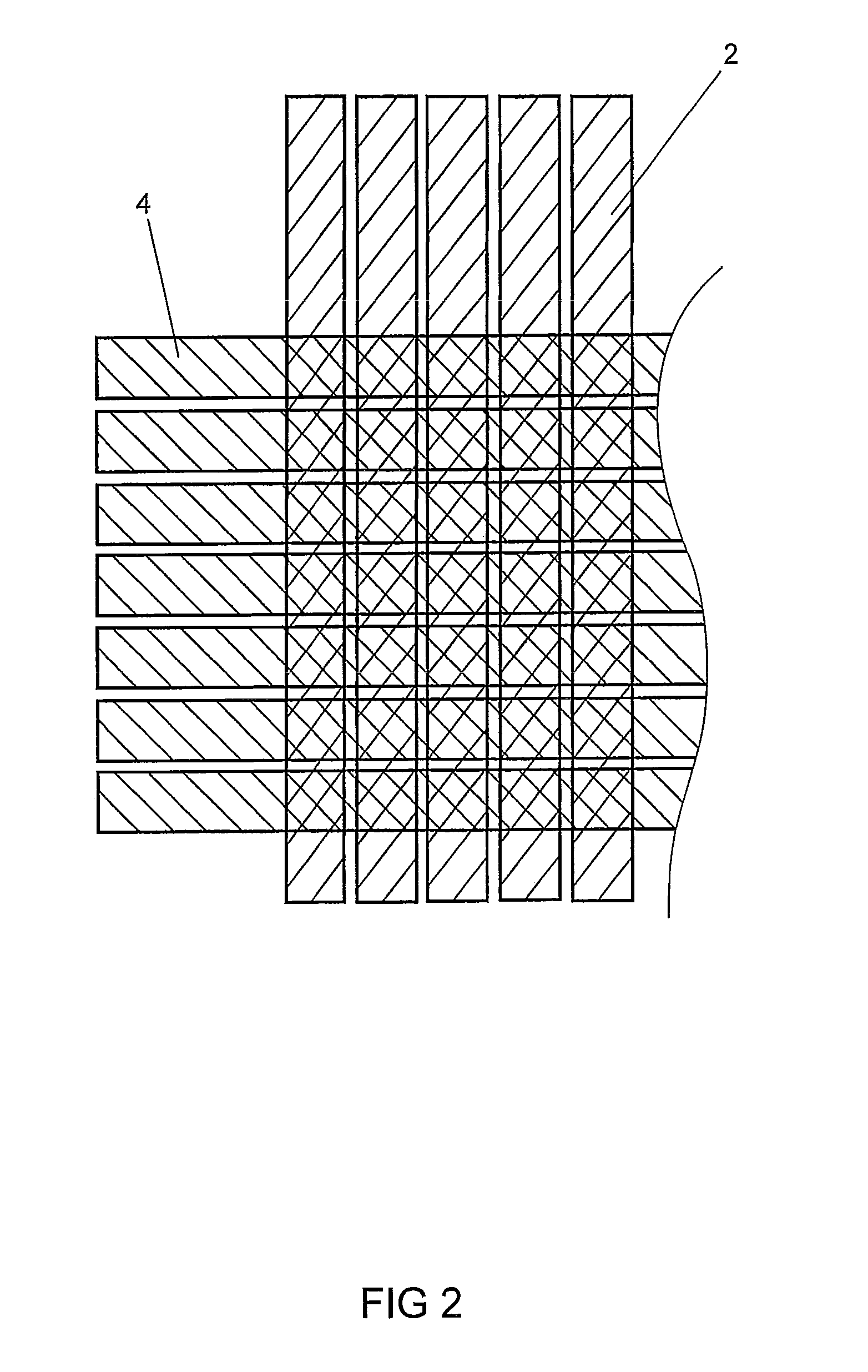
[0038]The active element based on the present invention can be used for example for producing matrix displays for use in electronic equipment (computers, TVs, mobile phones, indicators etc.), and surfaces and surface coatings that change colour. An active element that is based on an electret emulsion described above and that contains particles of pre-polarized electret material as emulsion in neutral liquid and both poles of the particles are coloured with different colours, is placed between two layers of a display or surfac...


PUM

PropertyMeasurementUnit
densityaaaaaaaaaa
pressureaaaaaaaaaa
temperatureaaaaaaaaaa

Abstract

An active element that is based on an electret emulsion and that comprises particles of pre-polarized electret material as emulsion in neutral liquid and both poles of the particles are colored with different colors. For producing a neutral carrier liquid for the active element liquid fluorine carbon is used. For producing electret material for the active element solid polymerised fluorine carbon or electret wax is used. The active element is used for producing visual matrix displays, indicators, surfaces and surface coatings that change color by the application of a control voltage.

Description

TECHNICAL FIELD[0001]The present invention belongs to the field of active elements as surfaces and surface coatings that change colour by the application of a control voltage and to the field of electronic displays, more specifically to the field of elements as used in matrix displays and indicators.STATE OF THE ART[0002]Various elements are used to visualise images and information in different electronic displays that divide the displays into two main groups: active displays and passive displays.[0003]In passive displays a control signal changes the reflection level of the matrix particles and using external light will form the visible image; the light will be reflected or absorbed according to the electrical field that is created between the control electrodes. The energy consumption of passive displays is lower and they are easier to read in conditions of intense external light. The main weaknesses of passive displays compared to active displays are: low contrast levels, low view...

Claims


Application Information

Patent Timeline
Patent Type & Authority Patents(United States)
IPC IPC(8): H01C1/02C09B67/46
CPCG02B26/026G02B26/02
Inventor LIIV, JURI
Owner VISITRET DISPLAY OU
Learn More