Image processing method

a processing method and image technology, applied in the field of meshed model generation, can solve the problems of computational intractable problems, model generated in this way may not be efficient to process, etc., and achieve the effects of accurate high stress gradients at the point of impact, avoiding overlapping, and preserving suitability

Active Publication Date: 2013-02-26
SYNOPSYS INC
View PDF10 Cites 8 Cited by
  • Summary
  • Abstract
  • Description
  • Claims
  • Application Information

AI Technical Summary

Benefits of technology

[0013]At its most general, the invention provides a modification of the VOMAC mesh generation method for image data in which the mesh resolution can vary locally within the mesh whilst permitting control of the distortion of cells in the mesh to maintain suitability for performing finite element (or finite volume) analysis. Varying the mesh resolution may enable smaller elements to be located in regions of particular interest or activity when subsequently performing finite element (or finite volume) analysis using the mesh model. Such mesh refinement may be particularly advantageous in finite element and finite volume analyses in order to better approximate the response of the system in certain critical areas. For example, in a simulation of hitting a skull with a hammer on the forehead a fine mesh around the impact site is desirable to capture the high stress gradients at the point of impact accurately. Varying the mesh resolution may allow areas of relatively high geometric complexity to be captured without also increasing cell density in areas of lesser interest, where it may not be required. Moreover, in images where the properties of material being imaged is captured in the image data, the invention may permit variance of the mesh resolution to provide greater cell density for regions in which the properties vary substantially.
[0014]There are two principal advantages of a locally denser mesh: (a) it can capture locally more complex geometry, e.g. to improve geometric accuracy / fidelity, and (b) it can model better variations in field parameter in a subset of the mesh domain, either because this field parameter varies rapidly and hence many elements are required to accurately approximate / model it in that area or because there is a point of particular interest to the analyst who wishes more accurate results from his model in a particular portion of the model.
[0030]Calculating the variable distribution may include: designating an epicentre (e.g. focal point) in a region of interest; increasing the density of sampling points in a focal region around the epicentre; and decreasing the density of sampling points in a transition region beyond the focal region. The focal region may be a stable region with uniform cell density.
[0048]An example of a particular use of the invention is where the redistributing of sampling points is used to update the mesh on a model to follow a crack as it propagates throughout a structure. In other words, the particular area of interest is moving through the structure in this example; by moving the morphed portion with the crack it can be modelled more efficiently.

Problems solved by technology

A model generated in this way may not be efficient to process because it may be more finely meshed than required in some areas, i.e. not all portions of the mesh need to have the same density of cells.
Moreover, this approach may render the problem computationally intractable because of the large number of cells.

Method used


Image

  • Image processing method
  • Image processing method
  • Image processing method

Examples


Embodiment Construction

[0057]The present invention is concerned with generating meshed models from image data to permit finite element (or finite volume) analysis to be performed e.g. by using the cells of the mesh as the primitive units in the analysis. The examples below are based on 3D image data and 3D meshes, but the same principles are applicable to 2D image data and 2D meshes.

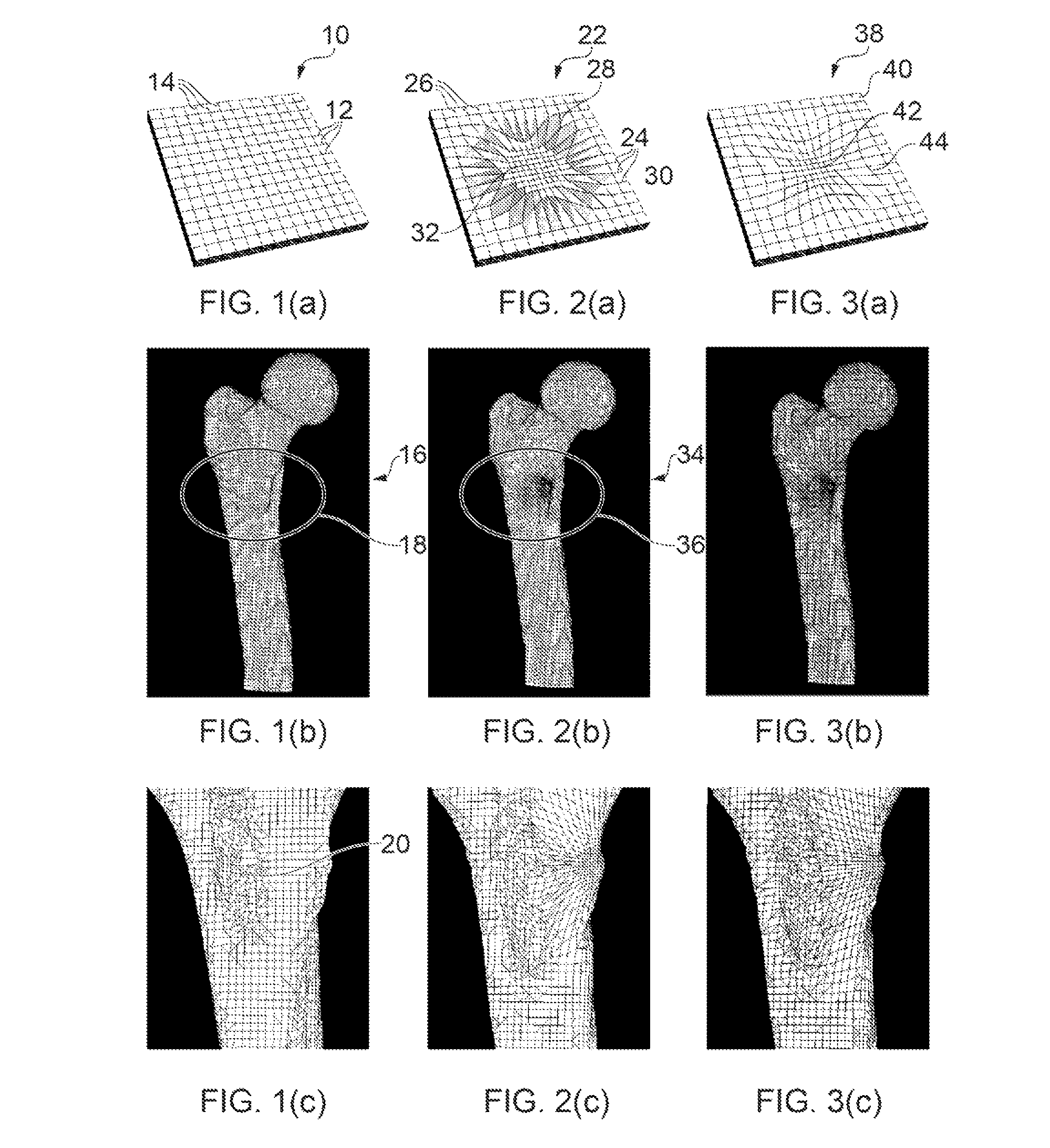
[0058]The examples illustrated in FIGS. 1-3 are based on a 3D image of the top half of a human femur, taken e.g. using a computerised tomography (CT) scanner or the like. However, the invention may be applied to any type of image data which involves sampling the space in which the object to be imaged resides.

[0059]The method of generating a mesh according to the invention involves sampling the image data at a plurality of sampling points. FIG. 1(a) shows one layer (i.e. a cross-section) of a uniform 3D sampling point distribution 10. FIG. 1(a) shows a grid of regularly spaced horizontal lines 12 and vertical lines 14 which int...


PUM


Abstract

A modified VOMAC mesh generation method for image data sampled from an actual object in which mesh resolution can vary locally within the mesh while permitting control of the distortion of cells in the mesh to maintain suitability for performing finite element (or finite volume) analysis on a representation of the object.The method includes computer-implemented instructions that calculate a variable sampling point distribution (SPD) in image data space, the variable SPD having localized variations in SPD within the image data space, and the distribution of sampling points having the same topology as a uniform SPD suitable for obtaining a regular structured is mesh. The method includes generating an indication of the magnitude of cell distortion between the generated mesh and the regular structured meshVarying the mesh resolution may enable smaller elements to be located in regions of particular interest or activity when subsequently performing analysis using the mesh model.

Description

[0001]This patent application claims the benefit of priority under 35 U.S.C. Section 119(e) from Great Britain Patent Application No. 0809588.7, filed on May 27, 2008, now pending and entitled “Image Processing Method,” which is hereby incorporated by reference in its entirety.FIELD OF THE INVENTION[0002]The invention relates to the generation of a meshed model from 2D or 3D image data, in which the model is suitable for use with finite element or finite volume simulation software.BACKGROUND TO THE INVENTION[0003]It is often desirable to generate models appropriate for carrying out physics-based simulations from image data. For example, a user may want to explore the temperature field generated by a cellular telephone around a human head. A model for the head may be generated from image data obtained from different medical imaging modalities e.g. Magnetic Resonance Imaging (MRI) scans. The most commonly used techniques for physics-based simulations, the finite element and finite vol...

Claims


Application Information

Patent Timeline
Patent Type & Authority Patents(United States)
IPC IPC(8): G06T17/20G06T17/00
CPCG06T3/40
Inventor YOUNG, PHILIPPE GEORGESBUI-XUAN, VIET
Owner SYNOPSYS INC
Why Eureka
Try Eureka