Process of controlling heavies in a recycle catalyst stream

a technology of recycle catalyst and recycle stream, which is applied in the direction of physical/chemical process catalyst, organic compound/hydride/coordination complex catalyst, separation process, etc., can solve the problems of high conversion rate, high cost of refrigeration unit, and condensation of overhead stream taken from vaporizer

Active Publication Date: 2013-03-26
DOW TECH INVESTMENTS +1
View PDF35 Cites 50 Cited by
  • Summary
  • Abstract
  • Description
  • Claims
  • Application Information

AI Technical Summary

Benefits of technology

[0116]Objects and advantages of this invention are further illustrated by the following examples, which also further clarify the invention. The particular materials and amounts thereof, as well as other conditions and details, recited in these examples should not be used to limit this invention. Rather they are illustrative of the whole invention. Other embodiments of the invention will be readily apparent to those skilled in the art from a consideration of this specification or practice of the invention as disclosed herein. Examples of the invention are numbered; while comparative samples, which are not examples of the invention, are designated alphabetically.

Problems solved by technology

Problems occur if 1-butene rich feeds that lead to high conversions in the hydroformylation are employed.
Disadvantageously, condensation of the overhead stream taken from the vaporizer becomes problematic at sub-atmospheric pressure.
Condensation temperatures of 0° C. or lower require a costly refrigeration unit and add complexity to the overall system.
Moreover, the use of sub-atmospheric pressure requires expensive equipment, such as compressors or turbines, having a high energy consumption.
Working at sub-atmospheric pressure bears a certain risk of air leakage into the apparatus which might cause deterioration of the catalyst activity and / or increase of catalyst decomposition.

Method used


Image

  • Process of controlling heavies in a recycle catalyst stream
  • Process of controlling heavies in a recycle catalyst stream
  • Process of controlling heavies in a recycle catalyst stream

Examples


specific embodiments

EXAMPLE 1 (E-1)

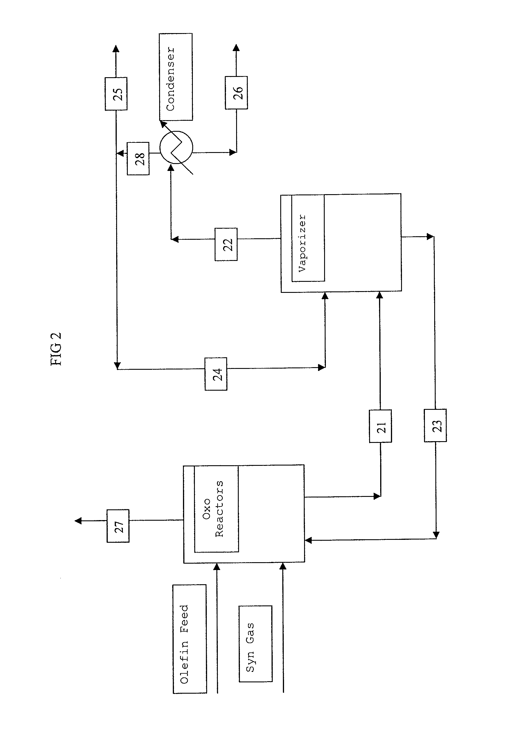
[0117]With reference to FIG. 2, a flow diagram is presented illustrating an embodiment of this invention for a hydroformylation process with subsequent separation of catalyst and aldehyde product from the hydroformylation product stream, and with recycle of a liquid catalyst stream back to the hydroformylation process. The process illustrated in FIG. 2 is modeled using ASPEN Plus software available from ASPEN Technology, Inc. of Cambridge, Mass., USA. The model assumes hydroformylation of a C4 raffinate II stream comprising 1-butene, 44 percent; cis-2-butene, 10 percent; trans-2-butene, 24 percent; isobutylene, 2 percent; and butane, 20 percent, by weight, with carbon monoxide and hydrogen in the presence of a rhodium-organobisphosphite ligand complex catalyst of Ligand D. As shown in Table 1, the ASPEN model provides mass balances for each stream of FIG. 2.

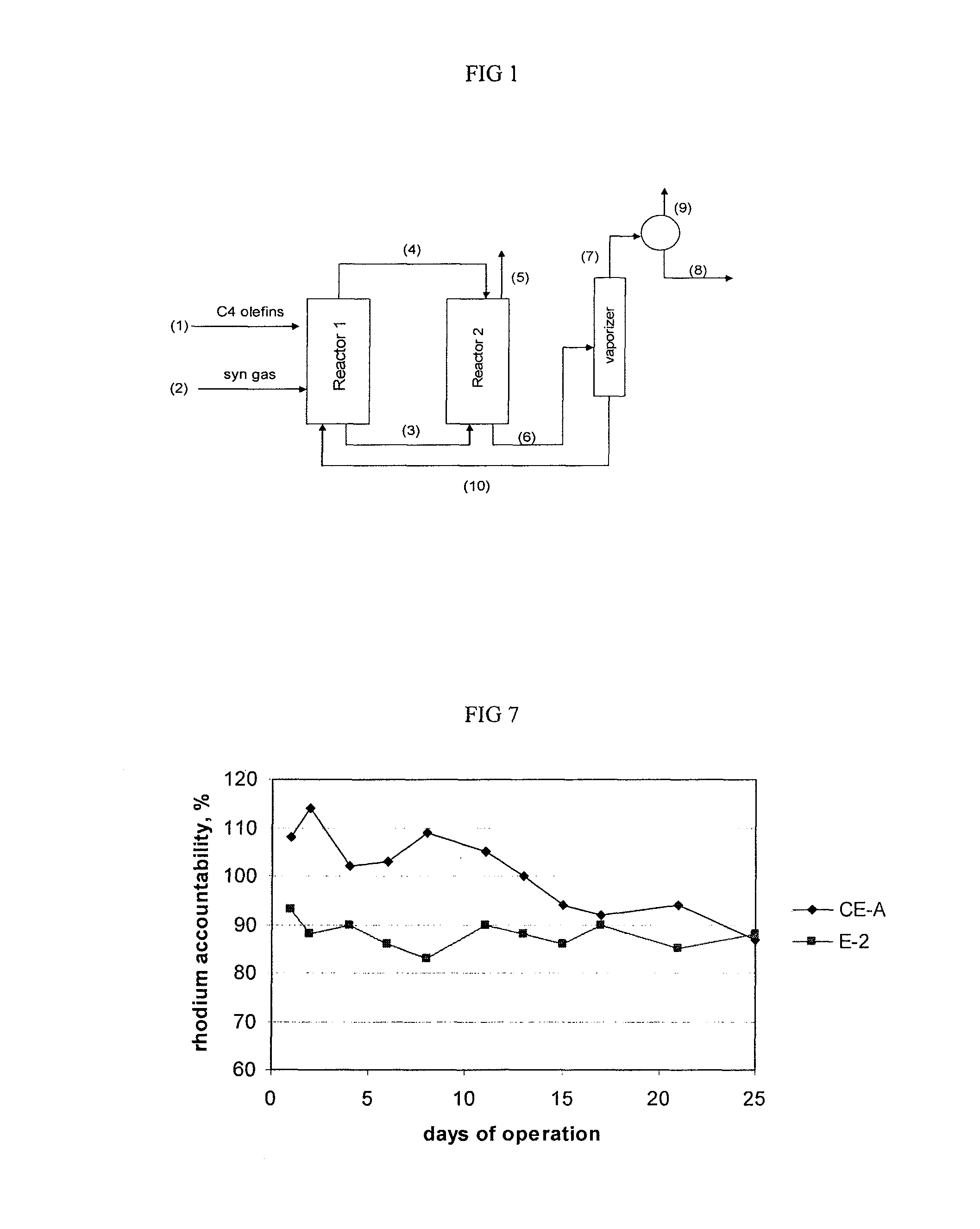
[0118]Referring to FIG. 2 and Table 1, the Oxo unit comprises two reactors connected in series. The C4 raffinate...

example 2 (

E-2)

[0122]The hydroformylation of a C4 raffinate mixture comprising 1-butene, trans-2-butene, cis-2-butene, and butane is conducted in a reactor system identical to the one depicted in FIG. 2. The Oxo unit comprises two reactors connected in series. The reaction mixture comprises about 30 percent butane; the balance being butenes in a 70 / 30 ratio of trans-2-butene to cis-2-butene, by weight. The catalyst comprises a rhodium-dioorganophosphite ligand complex catalyst of Ligand BB. The hydroformylation reaction conditions and vaporizer conditions are reported in Table 3.

[0123]

TABLE 3Example 2 Process ConditionsHydroformylation ConditionsReactor 1Reactor 2Ligand, wt %  3.6  2.7Rhodium, ppmw108 80Temperature, ° C.8060Pressure, psig (kPa)205 (1413)201 (1386)CO partial pressure, psi (kPa)65 (448)58 (400)H2 partial pressure, psi (kPa)69 (476)69 (476)1-Butene, partial pressure, psi0.29 (2.00) 0.13 (0.90) (kPa)trans-2-Butene, partial pressure, psi27.6 (190)  6.3 (43.4)cis-2-Butene, partial p...

example 3

[0134]Referring to FIG. 8, a liquid stream of reaction medium left the hydroformylation reactor via line (82), passed through a pressure reduction valve and entered flash vessel (83), operated at 6 bar (600 kPa). Reactor off gas was introduced in vessel (83) via line (81) also comprising a pressure reduction valve. A purge gas stream (84) was taken from the flash vessel (83). These gases (mainly consisting of synthesis gas, butene and butane) were sent to a condenser operated with chilled water to recover butenes and butanes and then sent to the off-gas header. The remaining liquid phase (ca. 70° C., 43.5 t / h) was taken from the separator vessel (83) and conveyed via line (85) into the falling film evaporator (86), heated with hot water. A stripping gas (50 t / h), consisting essentially of unreacted butenes and butanes, is introduced into the falling film evaporator (86) via line (87). Falling film evaporator (86) is maintained at ca. 2.5 bar (250 kPa) and ca. 110° C. Substantially a...


PUM

PropertyMeasurementUnit
temperatureaaaaaaaaaa
pressureaaaaaaaaaa

Abstract

A process of controlling heavies in a recycle catalyst stream, particularly, for use in a continuous hydroformylation process of converting an olefin with synthesis gas in the presence of a hydroformylation catalyst to form an aldehyde product stream with subsequent separation of the catalyst for recycle to the hydroformylation step. Heavies are controlled, and preferably reduced, by means of feeding a recycle gas stream, taken as a portion of an over-head stream from a condenser, back to a vaporizer wherein the aldehyde product stream is separated.

Description

CROSS REFERENCE TO RELATED APPLICATION[0001]This application claims priority to U.S. Provisional Patent Application No. 61 / 078,046, filed on Jul. 3, 2008, and which is hereby incorporated by reference.BACKGROUND OF THE INVENTION[0002]This invention pertains to a process of controlling heavies in a catalyst recycle stream. More particularly, this invention pertains to a two-stage process of hydroformylation and product-catalyst separation for controlling heavies in a catalyst recycle stream to the hydroformylation stage.[0003]It is well known in the art that aldehydes can be produced by reacting an olefinically unsaturated compound with carbon monoxide and hydrogen in the presence of a metal-organophosphorus ligand complex catalyst, and that preferred processes involve continuous hydroformylation and recycling of a catalyst solution containing a metal-organophosphorus ligand complex catalyst wherein the metal is selected from Groups 8, 9, or 10. Rhodium is a preferred Group 9 metal. ...

Claims


Application Information

Patent Timeline
Patent Type & Authority Patents(United States)
IPC IPC(8): C07C45/50
CPCC07C45/50C07C47/02C07C45/78Y02P20/584B01D1/22B01J31/18C07C2/36
Inventor COX, IRVIN B.EISENSCHMID, THOMAS C.PETERSON, RONALD R.PAPP, RAINERHERK, LUDWIGABATJOGLOU, ANTHONY G.
Owner DOW TECH INVESTMENTS
Why Eureka
Try Eureka