High speed power supply system

a power supply system and high-speed technology, applied in the direction of electric variable regulation, process and machine control, instruments, etc., can solve the problems of lack of control bandwidth, inadequacies of modulators, inefficient linear regulators, etc., to increase the control speed and accuracy of power supply, and minimize costs

Active Publication Date: 2013-03-26
QUANTANCE
View PDF72 Cites 9 Cited by
  • Summary
  • Abstract
  • Description
  • Claims
  • Application Information

AI Technical Summary

Benefits of technology

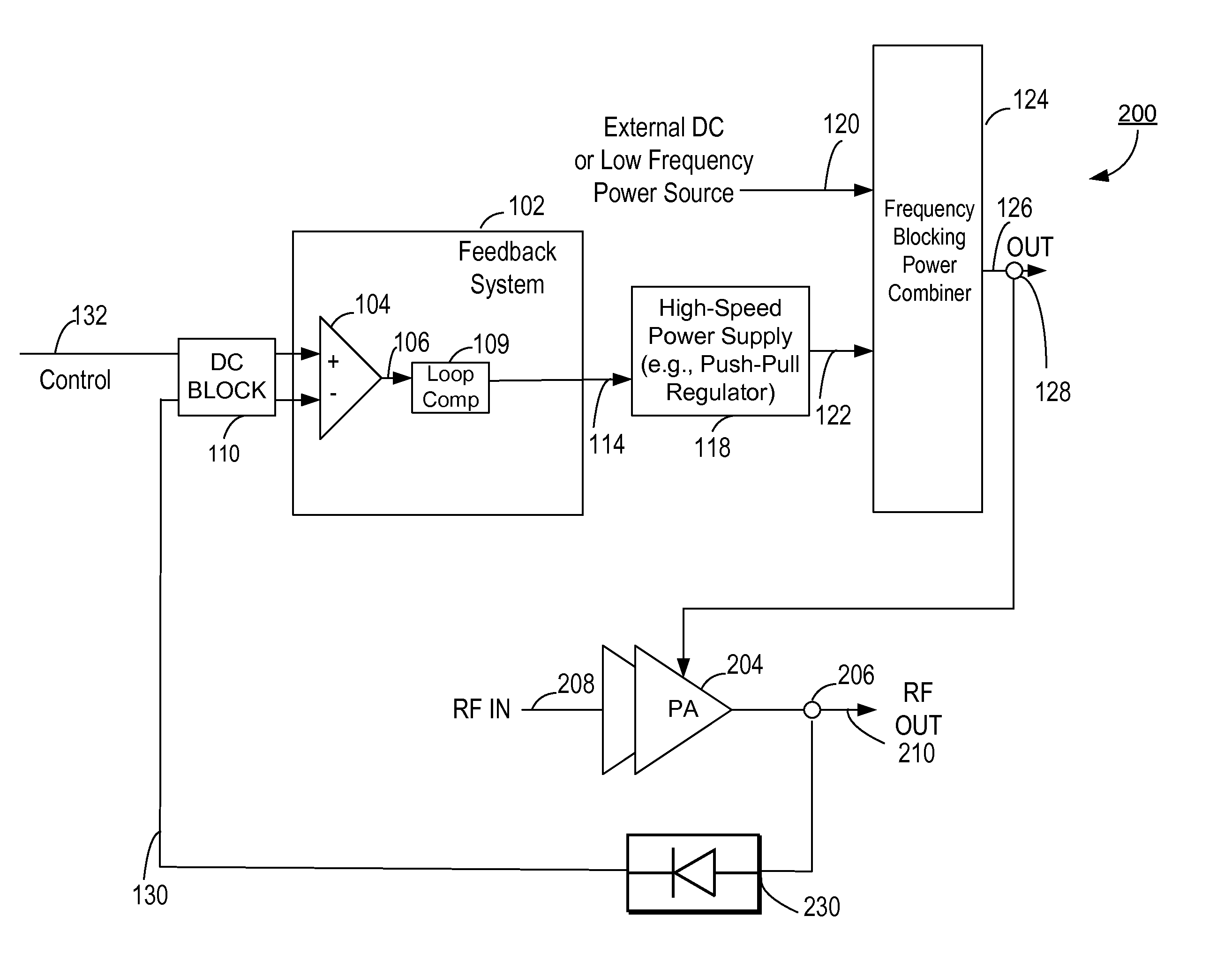
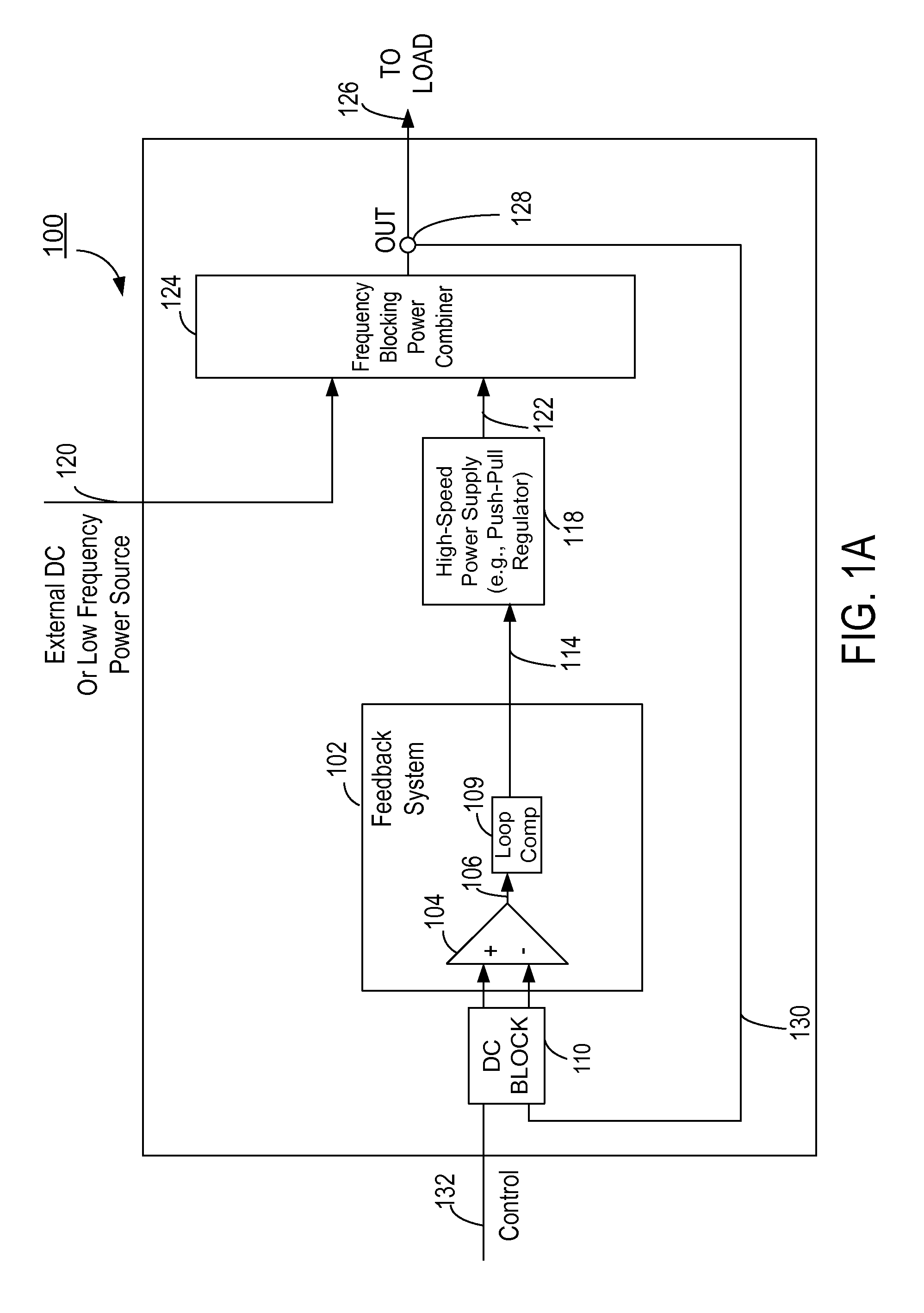
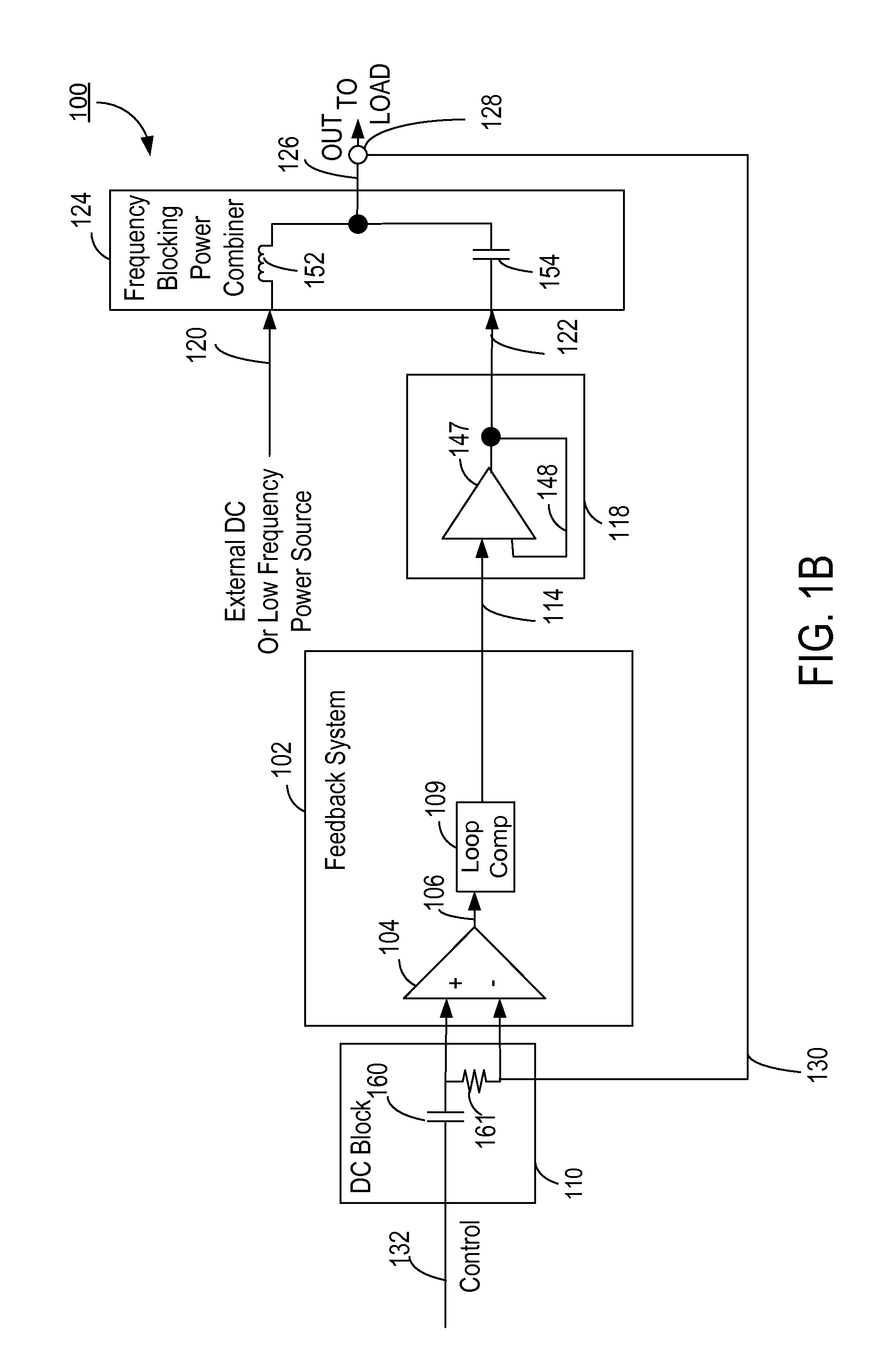
[0006]Embodiments of the present invention include a power supply system comprising a high-speed power supply providing a first output, operating in conjunction with an externally supplied DC source or low frequency power supply which provides a second output. A frequency blocking power combiner circuit combines the first and second outputs to generate a third output in order to drive a load, while providing frequency-selective isolation between the first and second outputs. A feedback circuit coupled to the combined, third output compares this combined, third output with a predetermined control signal and generates a control signal for controlling the high-speed power supply, based on a difference between the third output and the predetermined control signal. The feedback circuit does not control the DC source or the low frequency power supply, but controls only the high-speed power supply. The power supply system has the benefit of minimizing cost by harnessing an existing DC source or low frequency power supply to provide a significant portion of power to the load, while increasing the control speed and accuracy of the power supply by adding a high-speed power supply controlled in a closed-loop manner. The high-speed power supply can be a push-pull regulator.

Problems solved by technology

Such a linear regulator is inefficient, as linear regulators control the output voltage via a dissipative pass transistor.
However, these switching regulators lack the control bandwidth to modulate their output voltage at the rate needed to impose amplitude modulation in many modern radio systems, and therefore are not appropriate as modulators on their own.

Method used


Image

  • High speed power supply system
  • High speed power supply system
  • High speed power supply system

Examples


Embodiment Construction

[0015]The figures and the following description relate to preferred embodiments of the present invention by way of illustration only. It should be noted that from the following discussion, alternative embodiments of the structures and methods disclosed herein will be readily recognized as viable alternatives that may be employed without departing from the principles of the claimed invention.

[0016]Reference will now be made in detail to several embodiments of the present invention(s), examples of which are illustrated in the accompanying figures. It is noted that wherever practicable similar or like reference numbers may be used in the figures and may indicate similar or like functionality. The figures depict embodiments of the present invention for purposes of illustration only. One skilled in the art will readily recognize from the following description that alternative embodiments of the structures and methods illustrated herein may be employed without departing from the principle...


PUM


Abstract

A power supply system includes a high-speed power supply providing a first output, operating in conjunction with an externally supplied DC source or low frequency power supply which provides a second output. A frequency blocking power combiner circuit combines the first and second outputs to generate a third output in order to drive a load, while providing frequency-selective isolation between the first and second outputs. A feedback circuit coupled to the combined, third output compares this combined, third output with a predetermined control signal and generates a control signal for controlling the high-speed power supply, based on a difference between the third output and the predetermined control signal. The feedback circuit does not control the DC source or the low frequency power supply, but controls only the high-speed power supply.

Description

CROSS-REFERENCE TO RELATED APPLICATION[0001]This application claims priority under 35 U.S.C. §119(e) from U.S. Provisional Patent Application No. 61 / 165,377, entitled “High Speed Power Supply System,” filed on Mar. 31, 2009, which is incorporated by reference herein in its entirety.BACKGROUND OF THE INVENTION[0002]1. Field of the Invention[0003]The present invention relates to a high speed power supply system that can be used to power an RF PA (Radio Frequency Power Amplifier).[0004]2. Description of the Related Arts[0005]In certain electronic systems, there is a need for a high-speed power supply to complement an existing DC source or low frequency power supply. As an illustrative example, a radio system may include an EER (envelope elimination and restoration) transmitter, where the RF PA is fed by a power supply which modulates the PA's power supply voltage or bias, imposing amplitude modulation onto the RF carrier signal. Typically, the power supply feeding such a PA is a linear...

Claims


Application Information

Patent Timeline
Patent Type & Authority Patents(United States)
IPC IPC(8): H03G3/20
CPCH03F3/211H03F1/0211H03F1/0233H03F3/20H03F1/0238G05F1/575H03F3/19H03C1/00H03F1/0222H03F3/189H03F2200/411H03F2200/504H03F2203/21193H03F2200/451
Inventor DROGI, SERGE FRANCOISTOMASZ, MARTIN
Owner QUANTANCE
Why Eureka
Try Eureka