

Method of solid fuel beneficiation and transportation to thermoelectric power stations
a technology of solid fuel and thermoelectric power station, which is applied in the direction of fuels, chemistry apparatuses and processes, lighting and heating apparatus, etc., can solve the problems of significant irreversible water consumption, high energy consumption for evaporation, and unpractical power consumption
Inactive Publication Date: 2013-04-02
ENKHBOLD CHULUUN
View PDF13 Cites 0 Cited by
- Summary
- Abstract
- Description
- Claims
- Application Information
AI Technical Summary
Benefits of technology
The present invention aims to reduce energy consumption in mining, eliminate solid fuel loss, reduce water consumption, and protect the natural environment from pollution with dusty fuel. This is achieved through a technology that separates heavy liquid from products and operates the entire fuel-power generation complex in a closed cycle, using the drained final beneficiation tailings in the worked-out area without using any additional energy supplies. This results in ecological cleanness and prevents pollution by dusty fuel fractions.
Problems solved by technology
The above method is characterized by obviously unpractical power consumption for drawing waste rock from the coal mine to the surface as a part of rock mass and for bringing back waste beneficiation products to the place of their placement in the mined-out space, as well as by an intense environment pollution with coal dust during numerous transfers and transportations of the enriched solid fuel by railway to a thermoelectric power station owing to a strong blowing-out of dusty fractions of this dry free-flowing material by the wind.
However, the described method is characterized by a significant irreversible water consumption caused by the outlet of final tailings wetted with water out of the beneficiation system, as well as by high energy consumption for the evaporation of flows formed in the process of washing beneficiation products with water for the regeneration of the heavy water-salt medium.
Besides, the impossibility (for aero-logical reasons) of underground placement of the evaporation facility in the immediate vicinity of the placement of final tailings of beneficiation in the worked-out area, leads to the necessity of the delivery of the entire rock mass volume to the ground surface and, consequently, to the over-expenditure of power resources for the transportation of such an essential fraction of this ballast component.
Meanwhile, the delivery of dry enriched fuel from the ground-based beneficiation plant to the electric power station by railway, as already emphasized, is accompanied by easy blowing of its dusty fractions by the wind, which leads not only to significant loss of the delivered cargo, but also to an intense environment pollution with fuel dust, especially in places of transfer of this dusty material.
Method used
View moreImage
Smart ImageViewing Examples

Examples
Login to View More PUM
 Abstract
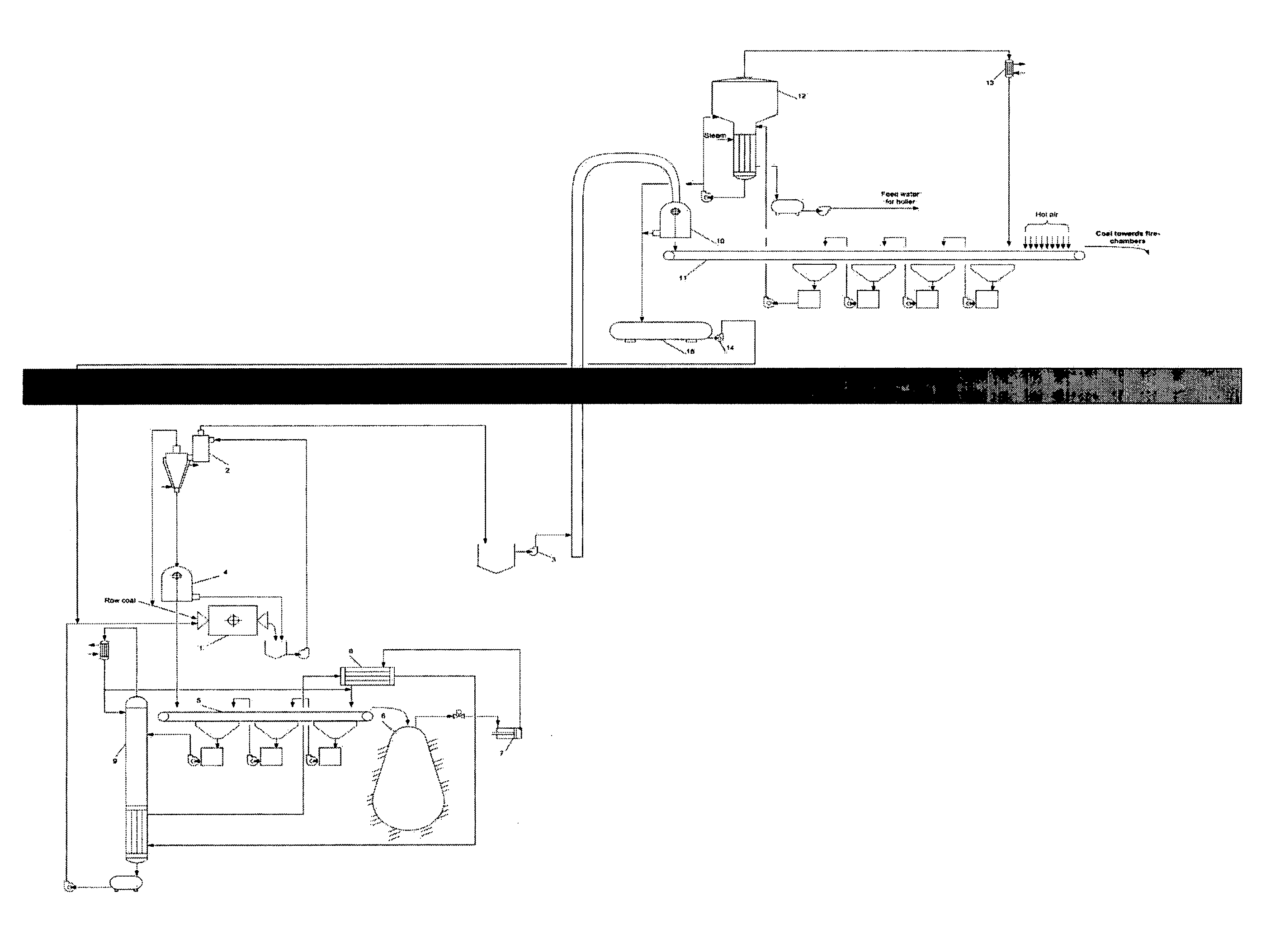
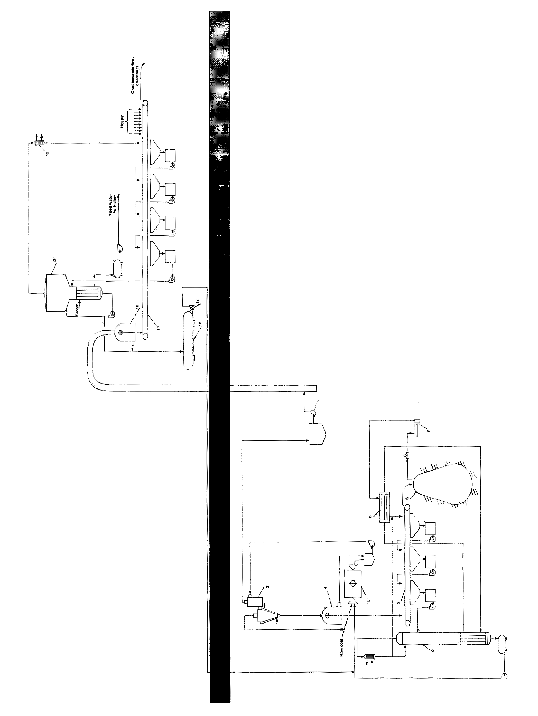
The invention is a process for the beneficiation and utilization of various kinds of coal and shale oil as a solid fuel for thermoelectric power stations. The beneficiation process is performed underground, near to the place of beneficiation waste stowing, using aqueous salt solution with a density between those of the target component and waste rock. The regeneration of heavy liquid from final beneficiation tailings is performed by washing with non-aqueous volatile liquid, with subsequent drying by the subsurface heat after placing these tailings in the worked-out space. The resulting vapors are compressed and condensed; thus regenerated non-aqueous liquid is returned for washing the beneficiation tailings, while effluents produced by washing are separated into aqueous and non-aqueous components by heat released at the liquefaction of the non-aqueous liquid vapors. The enriched solid fuel remaining in the floatable state is delivered by its flow to the thermo-electric power plant.
Description
TECHNICAL FIELD[0001]The present invention relates to mining and utilization of fossil energy minerals and can be applied to the beneficiation of various kinds of coal and shale oil produced for using as a solid fuel for thermoelectric power stations.BACKGROUND ART[0002]A gravitational method of beneficiation of coal to be used for power generation is known (see, for example, Mitchell, D. R. Coal Preparation, New York: American Institute of Mining, 1950; Tsiperovich M. V. Coal beneficiation in heavy media, Moscow: Metallurgizdat, 1953).[0003]According to this method, rock mass produced in the coalface is delivered by underground mine transport to the shaft bottom and then lifted to the surface using mine pulling unit, crushed and submerged into a liquid medium with the density intermediate between those of the fossil fuel and the waste rock, which represents powdery magnetite suspension in water. As a result, the solid fuel, as the lightest component of this system, floats in this h...
Claims
Login to View More Application Information
Patent Timeline
 Patent Type & AuthorityPatents(United States)
IPC IPC(8): B03B9/00
CPCB03B5/30F23K1/00C10L9/10B03B9/005
InventorENKHBOLD, CHULUUNALEXSANDER, BRODT
OwnerENKHBOLD CHULUUN