
Carbon nanotube and nanofiber film-based membrane electrode assemblies

a carbon nanotube and film-based technology, applied in the field of membrane electrode assemblies, can solve the problems of failure to establish the three-phase boundary (tpb) between gas, electrolyte, fuel cell electrocatalyst, etc., and achieve the effects of improving electrical and/or mechanical properties of the structure, maximizing the three-phase reaction coefficient, and little or no binder

Active Publication Date: 2013-04-09
FLORIDA STATE UNIV RES FOUND INC
View PDF13 Cites 9 Cited by
  • Summary
  • Abstract
  • Description
  • Claims
  • Application Information

AI Technical Summary

Benefits of technology

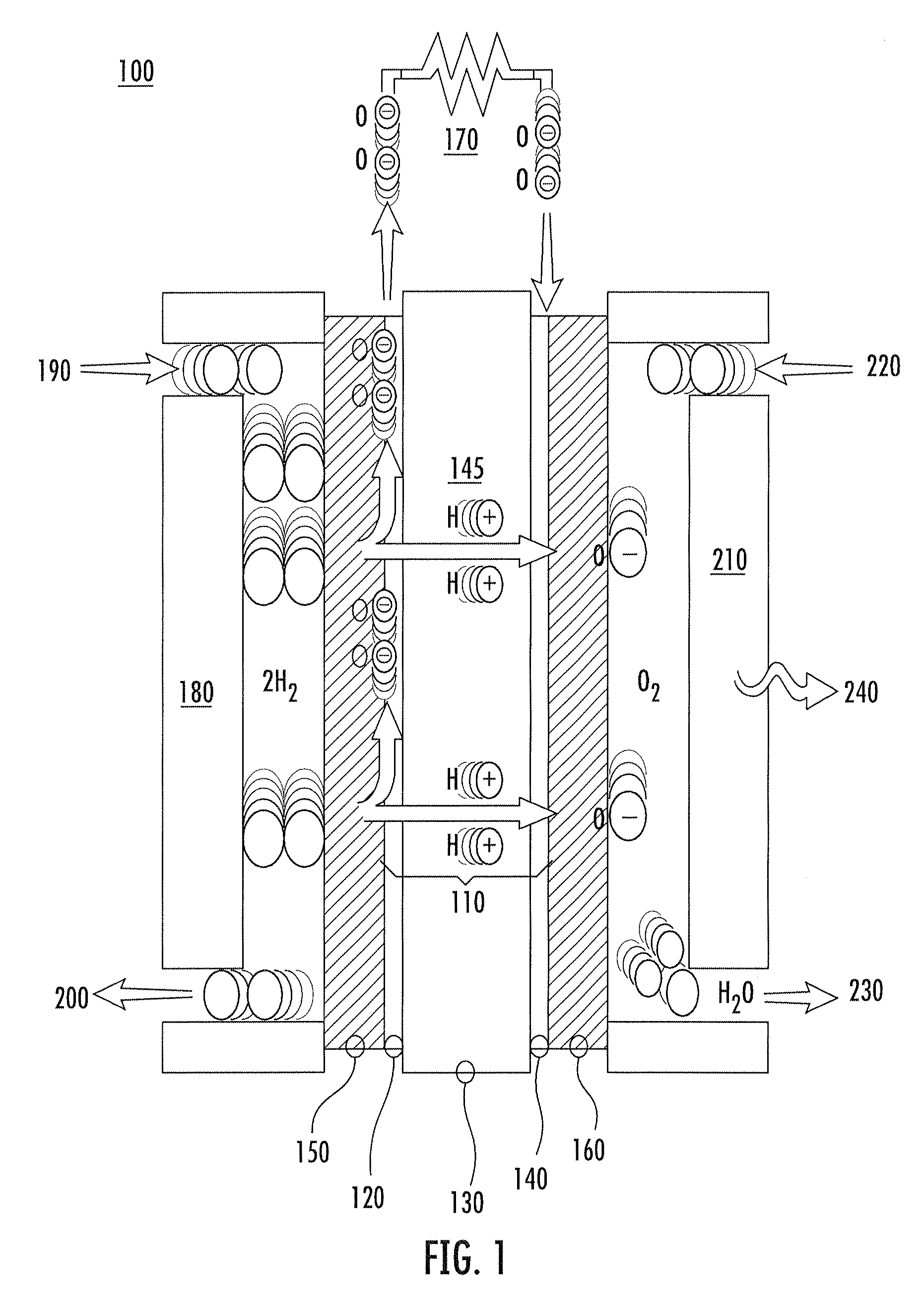
The invention is related to a new type of membrane electrode assembly (MEA) for fuel cells that uses a buckypaper with carbon nanotubes and / or nanofibers as the main component, without needing a binder. The buckypaper can also be treated with high temperature to improve its properties. By adjusting the starting materials and nanotube dispersion, the MEA can have a desired level of porosity, pore size, and electrical conductivity. The catalyst nanoparticles can be deposited directly at the most efficient sites on the buckypaper, resulting in better utilization of the catalyst and higher power output compared to conventionally-fabricated fuel cells. The new MEA also has enhanced oxidation resistance and longer service life.

Problems solved by technology

One obstacle to achieving this aim, however, is the fact that conventional catalyst supporting materials, such as carbon black Vulcan XC-72R, have numerous micropores in which Pt nanoparticles can become trapped.
This typically results in a failure in establishing the three-phase boundary (TPB) among gas, electrolytes, and the electrocatalyst of a fuel cell.
Moreover, carbon black can be corroded under the severe conditions inherent in the cathode of the fuel cell, resulting in low cell stability and reduced service life.
A significant problem inherent in the conventional process, however, is that the addition of the binder tends to isolate carbon nanotubes in the electrocatalyst layer, generally leading to poor electron transport and degradation or elimination of the Pt active surface.

Method used


Image

  • Carbon nanotube and nanofiber film-based membrane electrode assemblies
  • Carbon nanotube and nanofiber film-based membrane electrode assemblies
  • Carbon nanotube and nanofiber film-based membrane electrode assemblies

Examples


examples

Electrical Property Evaluations

[0055]Preparation and Characterization of Buckypaper

[0056]SWNTs 0.8-1.2 nm in diameter and 100-1000 nm long were obtained from Carbon Nanotechnologies Inc, while CNFs 100-200 nm in diameter and 30-100 μm long from Applied Sciences Inc were produced using a chemical vapor deposition (CVD) method. All materials were used as received without further purification.

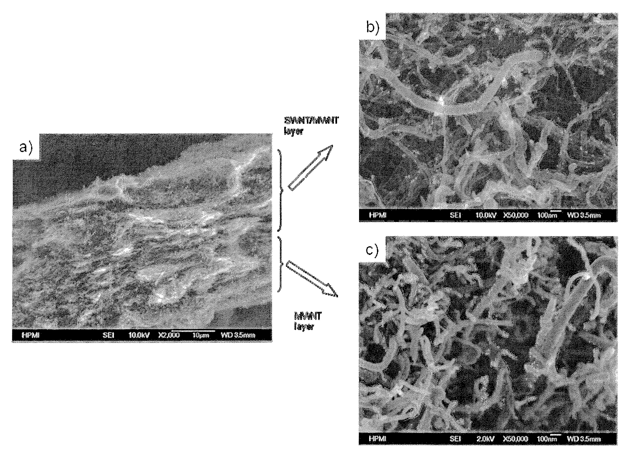
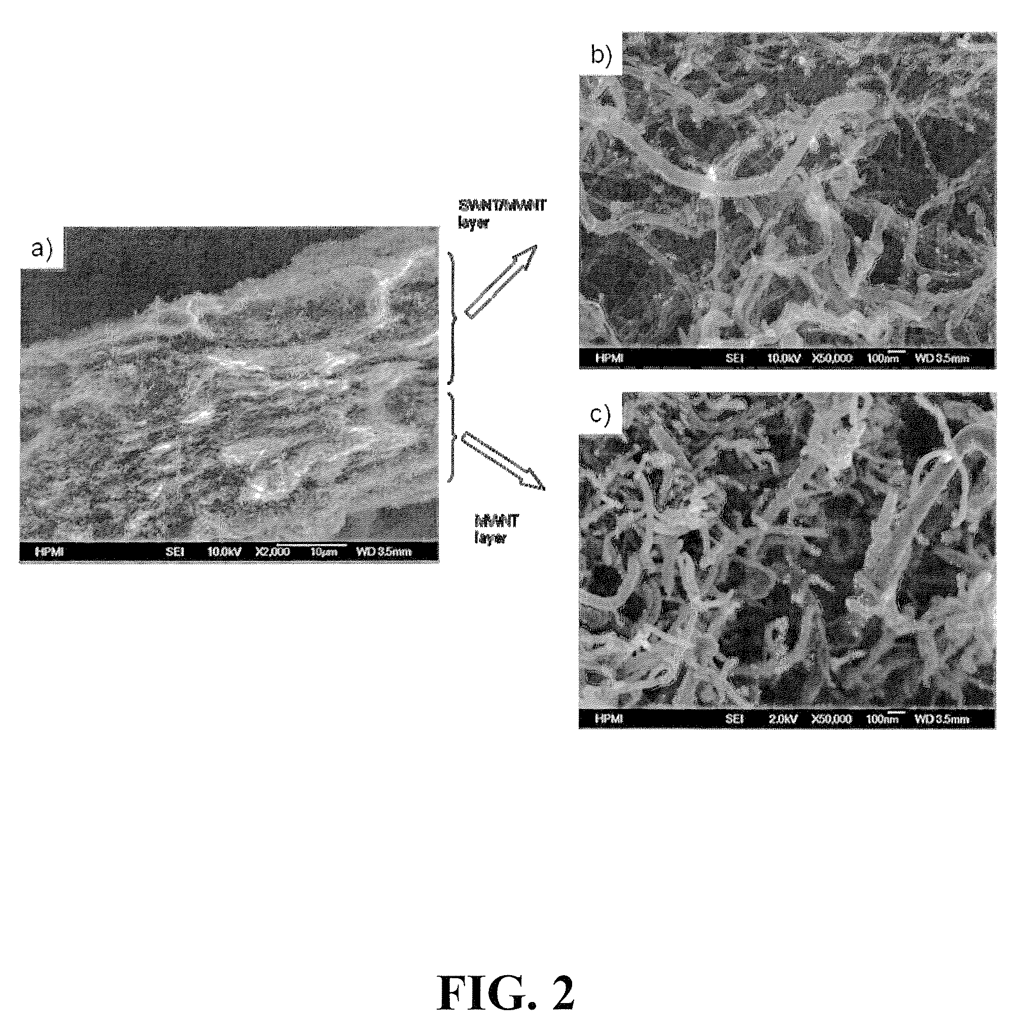
[0057]SWNT / CNF-mixed buckypaper sheets were produced using a vacuum filtration method. A mixture of SWNTs and CNFs (w / w 1:3 or 1:5), in 1000 ml deionized water was sonicated to form a homogenous dispersion by adding Triton-X (Dow) as a surfactant. The suspension was then filtered under a vacuum through a nylon membrane (Millipore) having a 0.45 μm pore size. The filtrate film was washed thoroughly with isopropanol to remove the residual surfactant. After drying, a thin film layer was peeled from the filtration membrane and a freestanding buckypaper (BP) was obtained.

[0058]A Tristar 3000 (Micrometr...


PUM

PropertyMeasurementUnit
diameteraaaaaaaaaa
lengthaaaaaaaaaa
diameteraaaaaaaaaa

Abstract

A membrane electrode assembly (MEA) for a fuel cell comprising a catalyst layer and a method of making the same. The catalyst layer can include a plurality of catalyst nanoparticles, e.g., platinum, disposed on buckypaper. The catalyst layer can have 1% or less binder prior to attachment to the membrane electrode assembly. The catalyst layer can include (a) single-wall nanotubes, small diameter multi-wall nanotubes, or both, and (b) large diameter multi-wall nanotubes, carbon nanofibers, or both. The ratio of (a) to (b) can range from 1:2 to 1:20. The catalyst layer can produce a surface area utilization efficiency of at least 60% and the platinum utilization efficiency can be 0.50 gPt / kW or less.

Description

CROSS-REFERENCE TO RELATED APPLICATIONS[0001]This application claims priority to U.S. Patent Application No. 61 / 081,851, filed Jul. 18, 2008, entitled “Carbon Nanotube and Nanofiber Film-Based Membrane Electrode Assemblies,” and is a continuation-in-part of U.S. patent application Ser. No. 11 / 670,687, filed Feb. 2, 2007, which claims priority to U.S. Patent Application No. 60 / 765,504, filed Feb. 2, 2006, the entirety of each is incorporated herein by reference.FIELD OF THE INVENTION[0002]The present invention is related to the field of membrane electrode assemblies for proton exchange membrane fuel cells.BACKGROUND OF THE INVENTION[0003]Fuel cells are regarded by many as a promising source of power for a wide array of devices, including vehicles, as well as a host of other portable and stationary applications. Fuel cells are capable of providing high energy efficiency and relatively rapid start-up. Moreover, fuel cells are capable of generating power without generating the types of ...

Claims


Application Information

Patent Timeline
Patent Type & Authority Patents(United States)
IPC IPC(8): H01M8/10H01M4/88
CPCB82Y30/00C04B35/83H01M8/0234H01M8/1004H01M4/926C04B2235/5288H01M4/8807Y10T428/30H01M8/0245Y02E60/521Y02E60/50Y02P70/50
Inventor ZHENG, JIAN-PINGLIANG, ZHIYONGWANG, BENZHANG, CHUNZHU, WEI
Owner FLORIDA STATE UNIV RES FOUND INC
Learn More