Method for fine-machining crankshafts and machining center therefor

a crankshaft and machining center technology, applied in the direction of milling equipment details, milling equipment, large fixed members, etc., can solve the problems of camshafts or crankshafts being subjected, certain distortion may occur,

Active Publication Date: 2013-04-16
GEBR HELLER MASCHFAB GMBH
View PDF7 Cites 2 Cited by
  • Summary
  • Abstract
  • Description
  • Claims
  • Application Information

AI Technical Summary

Benefits of technology

[0019]With the division of fine-machining procedures into a first machining succession for main shaft bearings and crank bearings and possibly for lapped bearings, stop surfaces and flange diameters and a second machining succession for flange and shaft end bores and shaft end outside diameter each functional surface can be machined in a single machining procedure in accordance with the manufacturing drawings, that is, without re-mounting of the shaft, which improves the machining quality and accuracy. The determination in which mounting setup, that is in which machining center the respective flange and outer shaft end surfaces are machined can be decided for each particular case. It depends on the type of crankshaft to be machined.
[0040]The rotational speed of the milling tool is at least 500 times and preferably at least 1000 times the speed of the camshaft. Furthermore, it is preferably so set that the periodic cutting edge engagement with the surface being cut does not cause any vibration of the shaft that is that it is outside the characteristic frequency. In this connection, it may be considered to provide several cutting edges at the front side of the milling tool at irregular angular distances. Also this measure can reduce vibrations.

Problems solved by technology

Furthermore, the camshaft or crankshaft may have been subjected to a thermal hardening procedure wherein, like in the rolling procedure, a certain distortion may occur.

Method used


Image

  • Method for fine-machining crankshafts and machining center therefor
  • Method for fine-machining crankshafts and machining center therefor
  • Method for fine-machining crankshafts and machining center therefor

Examples


Embodiment Construction

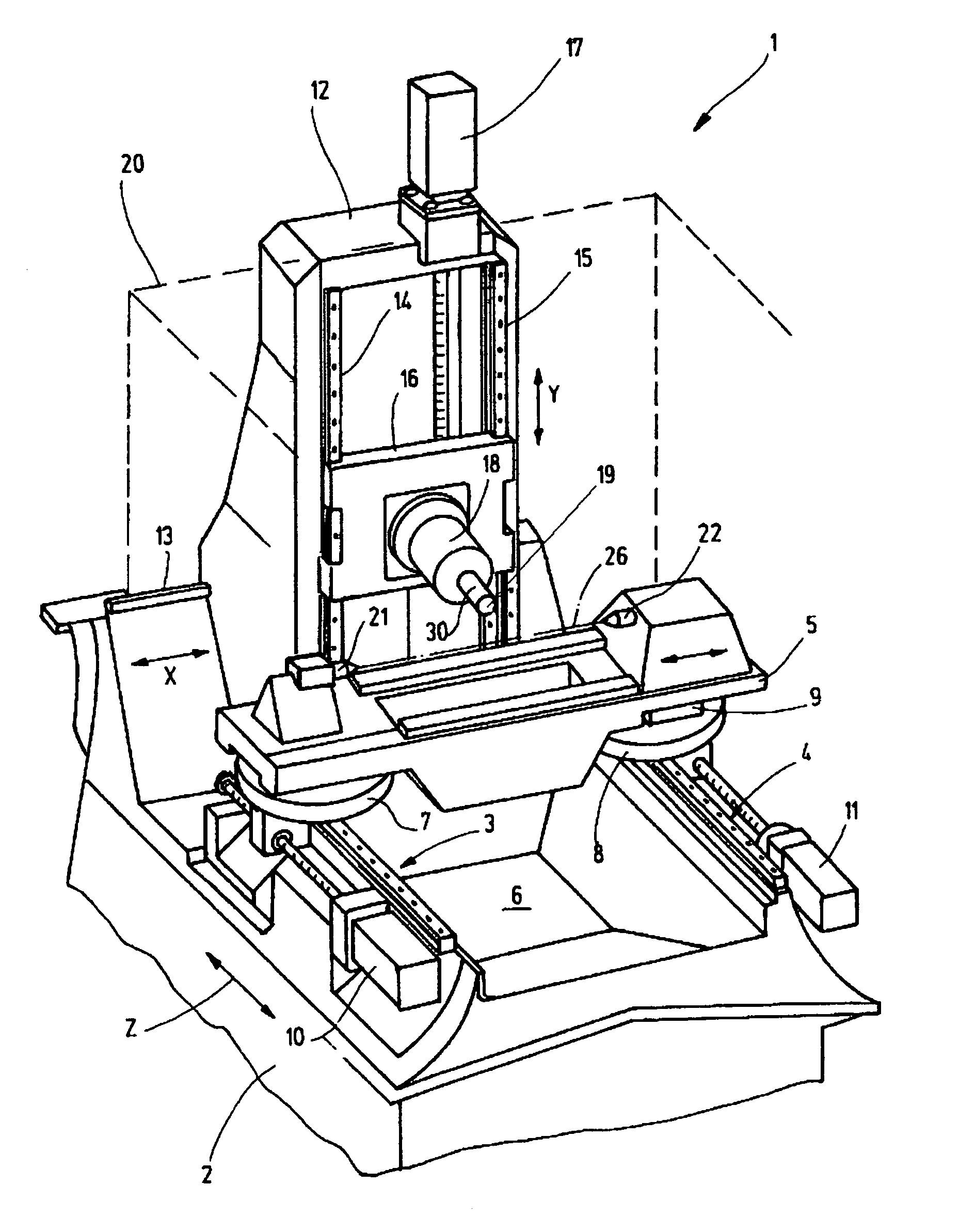
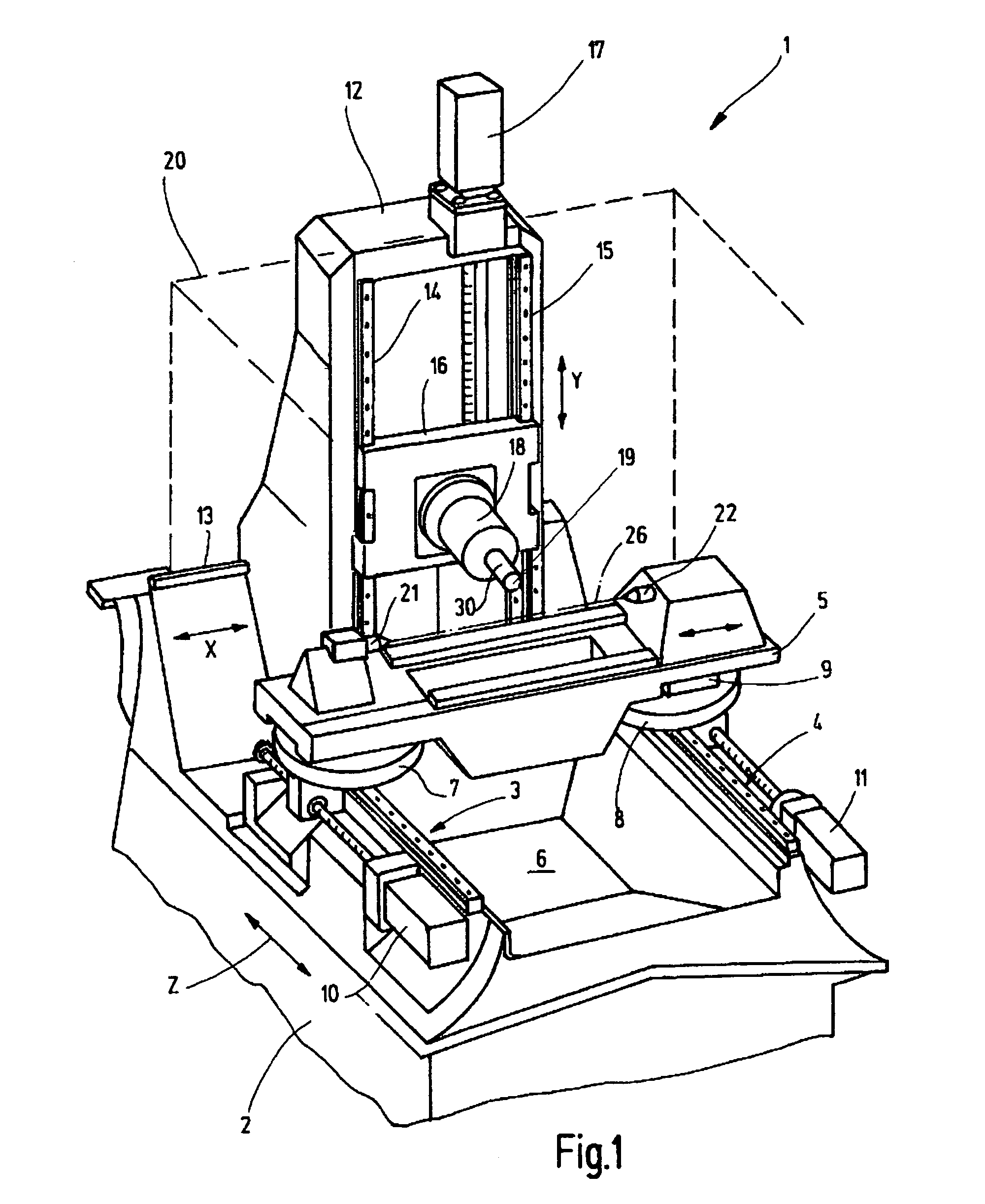
[0055]FIG. 1 shows a machining center 1 which comprises a machine base 2 with two linear guide tracks 3, 4 arranged in parallel spaced relationship for supporting a tool carrier 5. The two linear guide tracks 3, 4 which delimit therebetween a chip collection chamber 6 carry each a linearly movable carriage 7, 8 each of which is rotatably connected to the workpiece carrier 5. At least one of the carriages 7, 8, in the embodiment shown the carriage 8 includes a length compensation arrangement permitting a longitudinal movement of the workpiece carrier 5 with respect to the carriage 8.

[0056]The linear guide tracks 3, 4 are provided with control motors 10, 11 which can be operated independently for linearly moving the carriages 7, 8. The control motors 10, 11 can be controlled independently from a central machine control unit in order to move the workpiece carrier in a parallel manner or also to pivot it about a vertical axis. The movement direction provided by the linear guide arrangem...


PUM

PropertyMeasurementUnit
diameteraaaaaaaaaa
roughnessaaaaaaaaaa
Raaaaaaaaaaa

Abstract

A method and machine for machining shafts, such as crankshafts of an internal combustion engine wherein the shaft supported on a workpiece carrier rotatably about its axis and the carrier is movable relative to a milling tool adjustably supported on the machine, the bearing surfaces of the shaft are fine-machined by a milling tool taking into consideration the resiliency and the bending of the shaft by the engagement force of the milling tool during fine cutting of the bearing surfaces in the various angular rations of the shaft and the axial bearing location between the shaft ends so as to provide for a perfect final round cutting of the bearings without the need for wet grinding. The fine machining is preferably achieved by dry machining and orthogonal rotational milling, all main bearings and lifting bearings being machined in a single clamping from the rough machining dimensions to the final dimension. For a second machining sequence, some of the main bearings and lifting bearings are used as clamping surfaces.

Description

CROSS-REFERENCE TO RELATED APPLICATION[0001]This is a continuation-in-part application of pending international application PCT / EP2005 / 008083 filed Jul. 22, 2005.BACKGROUND OF THE INVENTION[0002]The invention relates to a method and machine for fine machining shafts such as crankshafts with center bearings and eccentric bearings which are both machined in a single machining setup.[0003]As summarized in DE 197 14 677 C2, crankshafts are conventionally often manufactured in a method whereby material was removed from the bearing locations of the originally formed, that is cast or forged, crankshaft in three subsequent machining procedures. The first machining step involved a rough cut with a geometrically determined cutting shape. Various processes were used herefor such as form cutting, milling, inside milling, outside milling etc. The material removal is in the millimeter range. The desired bearing diameters are formed with an excess diameter of a few tenths of a millimeter.[0004]Thi...

Claims


Application Information

Patent Timeline
Patent Type & Authority Patents(United States)
IPC IPC(8): B23C3/16
CPCB23C3/06B23C3/08B23Q1/4866B23Q1/44Y10T409/305544Y10T409/303808
Inventor FAIGLE, BERNDMARKER, WOLFGANG
Owner GEBR HELLER MASCHFAB GMBH
Why Eureka
Try Eureka