Removal equipment and method for the storage facility for transuranium compounds

a technology of transuranium compounds and equipment, which is applied in the field of large-scale removal of transuranium compound storage facilities, can solve the problems of contaminated equipment and piping in the two glove boxes, the inability to move the glove box out, and the contamination of the interior surface of the glove box, so as to achieve effective prevention of leakage of contamination, stable airflow, and low airborne concentration

Inactive Publication Date: 2013-04-16
INST NUCLEAR ENERGY RES ROCAEC
View PDF2 Cites 0 Cited by
  • Summary
  • Abstract
  • Description
  • Claims
  • Application Information

AI Technical Summary

Benefits of technology

[0008](2) Frame support and panel materials, such as load capacity, transparent and fire-resistance etc., are specially planned and designed; the panel transparency allows commanders outside the tent to keep up with the status of radioactive workers inside the tent and timely provide support during an incident in the removal process.
[0009](3) The inner panel of the quarantine tent is designed with smoothness and flatness. After completion of each batch-wise operation, panel surface cleaning and detection are conducted (the panel can be covered by PVC cloth, which will be replaced after completion of each batch-wise operation), to lower airborne concentration.
[0010](4) It is designed to have three “personnel entry-exit” rooms, which allow the workers to measure contamination and change clothes. The three rooms maintain stable airflow, sufficient air exchange to meet negative pressure requirement and effectively prevent leak of α contamination.
[0011](5) It is designed to have two “large object removal” rooms for removal of large objects, such as sedimentation tank, glove box panel, steel sheet etc., after the glove box is removed. The two rooms maintain stable airflow, sufficient air exchange to meet negative pressure requirement and effectively prevent leak of α contamination.
[0015]Since the removal of large-scale transuranium glove box adopts “In-Site Cutting Technique”, it is necessary to build an alpha airtight quarantine tent around the glove box to maintain stable airflow and sufficient air exchange to meet negative pressure requirements and effectively prevent leak of α contamination. A negative pressure ventilation system is installed to work with the quarantine tent. The negative pressure ventilation system includes blower, exhaust fan, HEPA filter, various butterfly valve / air damper and air duct to assure the negative pressure gradient in the tent −6 mmW.G.→−8 mmW.G.→−10 mmW.G.→−10 mmW.G.→−15 mmW.G.→−30 mmW.G. and enable the gas flow from low contamination area to high contamination area. This can effectively prevent spreading of a contamination and increase safety for the transuranium disposal equipment that is not in service. The design for the airtight quarantine tent and ventilation system is to meet the requirements in Table 1 for large-scale transuranium equipment removal process and radiation prevention and safety.
[0021](3) The negative pressure butterfly type control valves for the exhaust fan and the blower are located before the exhaust fan HEPA filter and after blower HEPA filter, and at the inlets and return air inlet for each air-lock room. So when the system starts, the related solenoid valve is energized to open the control valve. The control valve is failure type, which shuts off automatically when the power is out and therefore can prevent flow back of α contamination air from “removal operation section” and spreading into every air duck and G32 room.

Problems solved by technology

Due to the large size and interior structure, the glove box cannot be moved out at one time.
The equipments and piping in the two glove boxes and the interior surface of the glove boxes are all contaminated by transuranium isotopes.

Method used


Image

  • Removal equipment and method for the storage facility for transuranium compounds

Examples


Embodiment Construction

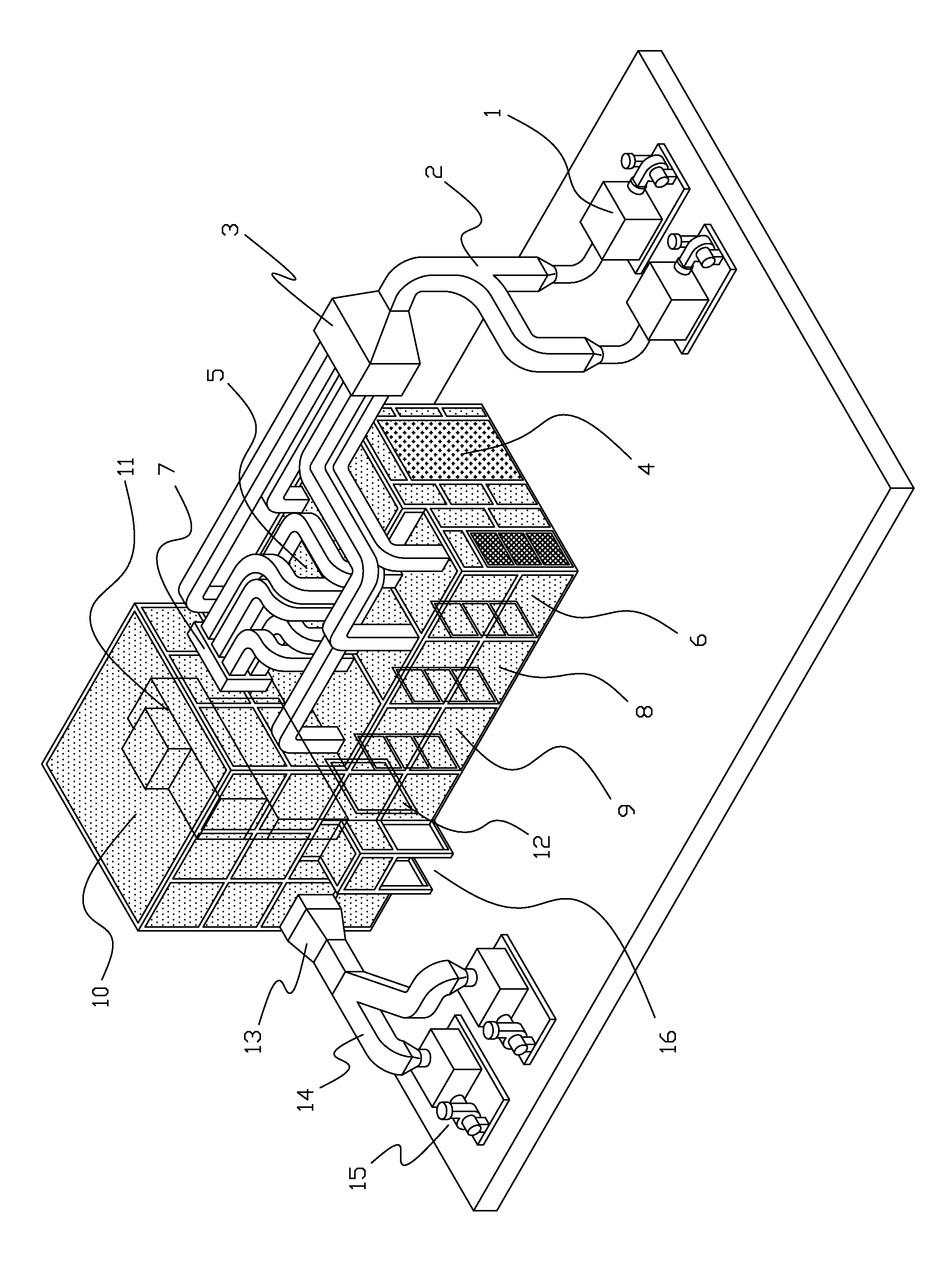
[0030]FIGURE is the diagram for the quarantine tent and the negative pressure ventilation system removed from the transuranium glove box of Unit 21. As shown in the FIGURE, the operation range for the quarantine tent includes: removal operation section 10 (C1), personnel entry / exit room 19 (A1), personnel entry / exit room 28 (A2), personnel entry / exit room 36 (A3), large object transfer room 15 (B1), large object transfer room 24 (B2). There are six sections in total, which are one removal operation section 10 and five air-lock rooms.

[0031]The quarantine tent includes a removal operation section 10 (C1) and five airlock rooms (A1, A2, A3, B1 and B2). To maintain a gradient for the air flow in the quarantine tent from low negative pressure to high negative pressure and effectively control a particle direction in airflow, it is necessary to build a negative pressure ventilation system to work with the quarantine tent. The work scope for the negative pressure ventilation system includes...


PUM


Abstract

A nuclear chemistry laboratory adopts In-site Cutting Technique to remove the large-scale glove box contaminated by transuranium compounds. During removal operation, to prevent further spreading of contamination, it is necessary to build an alpha airtight quarantine tent around the glove box that is ready to be cut. Each section of the quarantine tent maintains a stable airflow and sufficient air exchange to meet negative pressure requirements and effectively prevent leak of α contamination. It is necessary to install a negative pressure ventilation system to assure the operation of the quarantine tent that has a pressure gradient and allows airflow from low contamination area to high contamination area to effectively prevent spreading of α contamination and also increase the safety for the transuranium contaminated glove box that is not in service.

Description

BACKGROUND OF THE INVENTION[0001]1. Field of the Invention[0002]The invention relates to a disposal program for large-scale storage facility for transuranium compounds, especially a removal process for a large-scale glove box contaminated by transuranium compounds. It is to establish the quarantine tent and the negative pressure ventilation system in a removal process for a large-scale glove box contaminated by transuranium compounds to attain the α contamination quarantine effect and the radiation safety and prevention requirements.[0003]2. Description of the Prior Art[0004]The integrated removal technology for medium-scale and small-scale glove boxes of α contamination involves cutting and sealing of the peripheral piping for the glove boxes. The glove box is put into a large PVC bag. Then the bag is sealed and wrapped by a large tape to prevent the leak of α contamination from the glove box and minimize the generation of unnecessary secondary wastes concerning “radiation safety a...

Claims


Application Information

Patent Timeline
Patent Type & Authority Patents(United States)
IPC IPC(8): B08B17/00F24F7/003
CPCG21F9/22F24F7/00F24F11/0001G21F7/015G21F9/001F24F2011/0005F24F7/003
Inventor TSIA, CHENG-TOLIANG, KUO-LONGWU, JIANG-TZUANLEE, CHUNG-SHIN
Owner INST NUCLEAR ENERGY RES ROCAEC
Why Eureka
Try Eureka