
Multi-frequency, noise optimized active antenna

a noise optimization and active antenna technology, applied in the field of wireless communication, can solve the problems of not revealing the use of an impedance transformer, difficult task of antenna matching across the wide range of frequencies, and inconvenient operation of antenna design and prior art antennas.

Inactive Publication Date: 2013-04-16
KYOCERA AVX COMPONENTS (SAN DIEGO) INC
View PDF7 Cites 3 Cited by
  • Summary
  • Abstract
  • Description
  • Claims
  • Application Information

AI Technical Summary

Benefits of technology

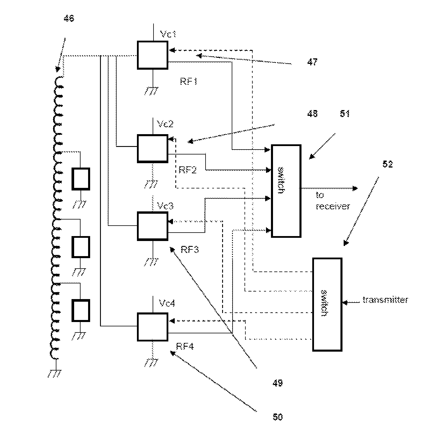
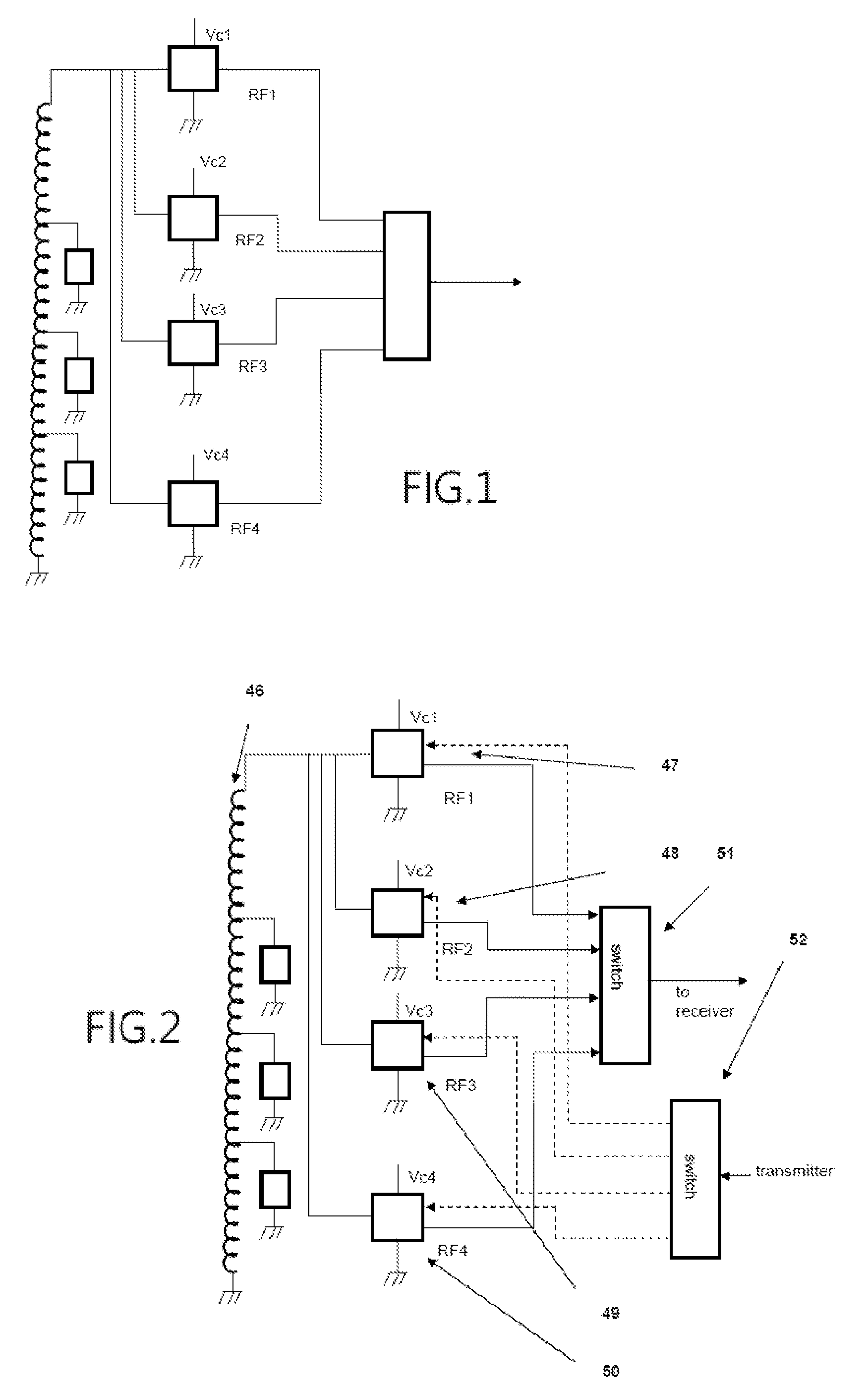
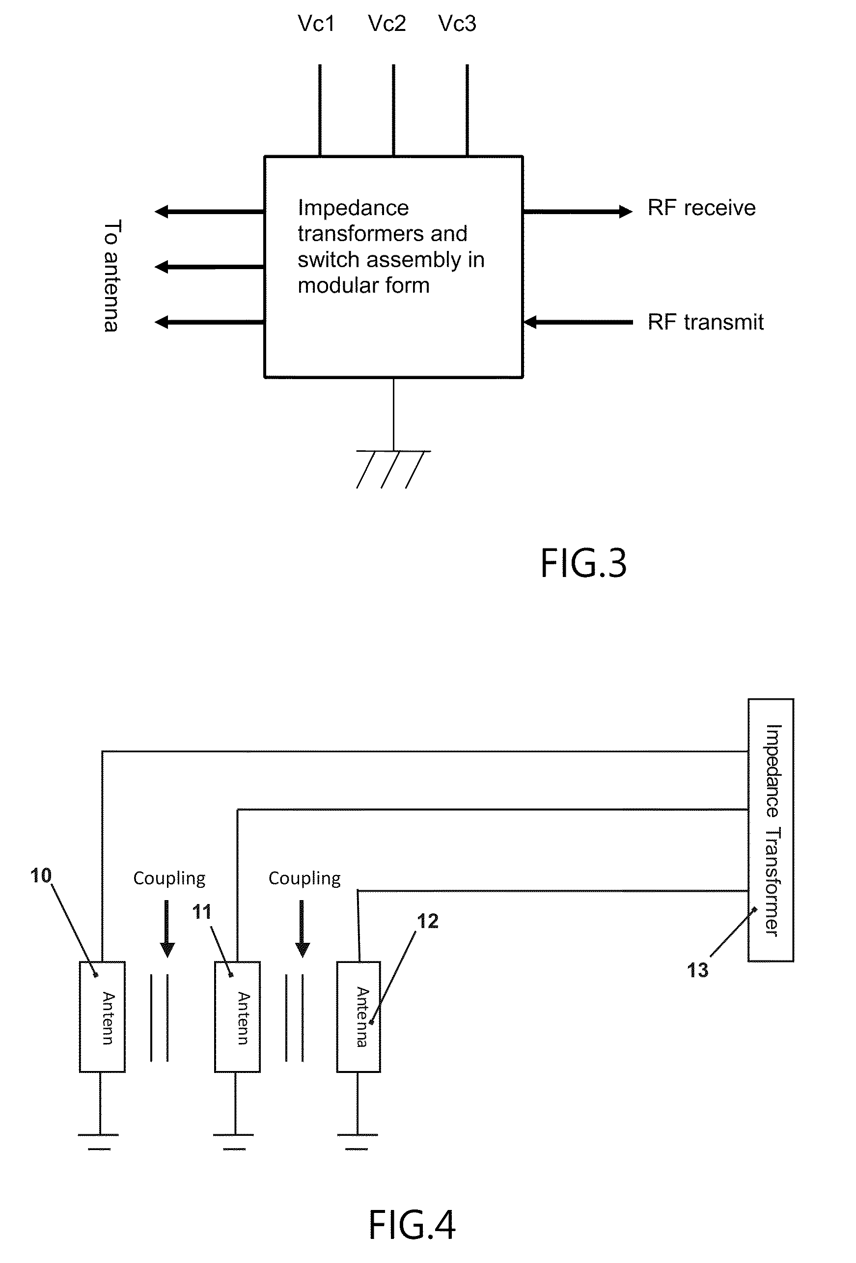
The present invention provides an improved antenna system for portable wireless devices that can efficiently operate over FM and DVB-H frequencies while keeping up with the design requirements of modern devices. The antenna system uses actively tuned narrow instantaneous bandwidths which greatly improves radiation efficiency compared to traditional antennas. The conductive loop is loaded with ferrite material to increase the electrical performance of the loop. An active tuning component is connected to the ferrite loaded loop antenna to cancel its reactance, and an impedance transformer is connected to the loop to reduce its impedance for optimal coupling to a receiver. The impedance transformer can be a MOSFET or any other semiconductor capable of transforming high impedance to lower impedance with small signal voltage losses.

Problems solved by technology

The reduced volume allowed for an internal antenna coupled with the strict requirement that the internal FM and DVB-H antennas must not interfere with the main antenna or other ancillary antennas in the handset makes the task of antenna matching across the wide range of frequencies quite difficult.
Current market-available antenna designs and prior art antennas are not suitable for overcoming the aforementioned problems.
Although useful in many applications, the '669 application does not disclose the use of an impedance transformer for matching the antenna with a transceiver.
Antennas commonly known and available which generally cover the entire frequency range tend to display inadequate antenna radiation efficiency at a fixed volume.

Method used


Image

  • Multi-frequency, noise optimized active antenna
  • Multi-frequency, noise optimized active antenna
  • Multi-frequency, noise optimized active antenna

Examples


Embodiment Construction

[0029]In the following description, for purposes of explanation and not limitation, details and descriptions are set forth in order to provide a thorough understanding of the present invention. However, it will be apparent to those skilled in the art that the present invention may be practiced in other embodiments that depart from these details and descriptions.

[0030]In a general embodiment of the present invention, an antenna system is provided which comprises an antenna element, an active tuning component connected to the antenna element, and an impedance transformer. The antenna element and connected active tuning component define what is herein referred to as an active tuned element. The active tuned element is connected to the impedance transformer for matching the impedance of the antenna system with the impedance of a receiver, transmitter or transceiver. The impedance transformer should be connected to the active tuned element at a point of high voltage for maximum efficienc...


PUM


Abstract

A multi-frequency, noise optimized active antenna consisting of one or several actively tuned antennas optimized over incremental bandwidths and capable of tuning over a large total bandwidth. One or multiple impedance transformers are connected to the antennas at an optimal location, with the transformers acting to reduce the impedance for optimal coupling to a transceiver / receiver. Active components can be incorporated into the antenna structures to provide yet additional extension of the bandwidth along with increased optimization of antenna performance over the frequency range of the antenna. The radiating elements can be co-located with a ferrite material and / or active components coupled to the element to tune across a wide frequency range.

Description

FIELD OF THE INVENTION[0001]The present invention relates generally to the field of wireless communication. In particular, the present invention relates to an antenna for use within such wireless communication; and more specifically, the present invention provides an antenna system designed to transmit and receive data over a broad spectrum of instantaneous bandwidths for media applications within such wireless communication.BACKGROUND OF THE INVENTION[0002]The continual search for additional frequency bandwidth and efficiency from antennas in wireless systems points to the need for new approaches. Increasing frequency bandwidth of internal antennas for media applications in cell phones is a prime example. More specifically, FM radio and DVB-H TV reception are requirements in a large number of mobile phones. Antenna performance is a key parameter for good reception quality. Mobile handsets are very small compared to wavelengths at FM and DVB-H frequencies; accordingly the antennas u...

Claims


Application Information

Patent Timeline
Patent Type & Authority Patents(United States)
IPC IPC(8): H01Q1/50
CPCH01Q7/00H01Q9/16
Inventor FRIMAN, ALFSU, XIAOMENGDESCLOS, LAURENT
Owner KYOCERA AVX COMPONENTS (SAN DIEGO) INC
Learn More