Tube with reverse necking properties

a tubular structure and reverse necking technology, applied in the field of tubular structure improvement, can solve the problems of difficult or impossible to slide the plastic wrap off the mandrel, the necking can be problematic, and the mandrel is difficult or impossible to be slid off, so as to increase the diameter of the tube, increase the diameter, and increase the diameter

Active Publication Date: 2013-05-07
WL GORE & ASSOC INC
View PDF110 Cites 14 Cited by
  • Summary
  • Abstract
  • Description
  • Claims
  • Application Information

AI Technical Summary

Benefits of technology

[0014]The present invention is directed to an improved tubular structure that is adapted to increase in diameter when axial force is applied to the structure. This increase in diameter may be accomplished by constructing the tube from multiple layers of material that move relative to each other during axial elongation of the tube. The tube of the present invention can be used both to avoid problems in “necking” found in many prior tube devices, and to provide additional benefits that increases in diameter of the tube during axial elongation can provide. As such, the tube of the present invention may be useful as a manufacturing aid, as a deployment sheath (for example, to deliver medical devices), and in other applications that may benefit from easier tubular sheath removal.
[0018]Further defined, the present invention comprises a tubular device having a tubular structure with at least one helically-oriented element and a diameter. Application of axial force to the tubular device causes the helically-oriented element to at least partially unwind, increasing the diameter of the tubular device.
[0019]One of the advantages of the present invention is that it can be utilized as a single layer of uniform thickness. When used, for instance, to deploy medical devices, these properties are believed to provide important benefits over prior everted and / or pleated tubes. However, it should be appreciated that the present invention can be incorporated with either everted or pleated constructs (or both) to provide additional improved properties. In all these various iterations, the present invention provides the benefit of allowing delivery of a remotely deliverable medical device with smaller and more flexible profile, and deployment of the device with less tension and more accurate placement.

Problems solved by technology

This property is commonly referred to as “necking.” Such necking can be problematic in many applications.
For instance, if a plastic wrap is applied over a mandrel in a manufacturing process, pulling on the end of the plastic wrap to remove the wrap from the mandrel will result in the wrap necking down on the mandrel.
This often makes it difficult or impossible to slide the plastic wrap off the mandrel, requiring cutting of the wrap or distortion of the mandrel to separate the wrap.
Typically this requires using plastic tubes that resist necking, such as thicker and / or stiffer materials that can add undesirable profile to the device and / or reduce its flexibility and maneuverability within the body.
While everting sheaths can reduce the tension that must be applied to the constraining sleeve, they still can require considerable tension in order to pull the sheath over itself and the self-expanding device during deployment, resulting mainly from the friction of everted portion of the sheath rubbing against the non-everted portion of the sheath while the sheath is being removed.
To whatever degree the sleeve material necks down on the device during deployment, this further complicates device design.
The greater the tension needed to evert and remove the sheath, the more demanding it is for the medical staff to remove the sheath while trying to hold the apparatus in its exact position during deployment.
It is believed that these deficiencies of everting sheaths may have limited practical applications for such deployment methods.

Method used


Image

  • Tube with reverse necking properties
  • Tube with reverse necking properties
  • Tube with reverse necking properties

Examples


example 1

Uniaxially Oriented ePTFE Film

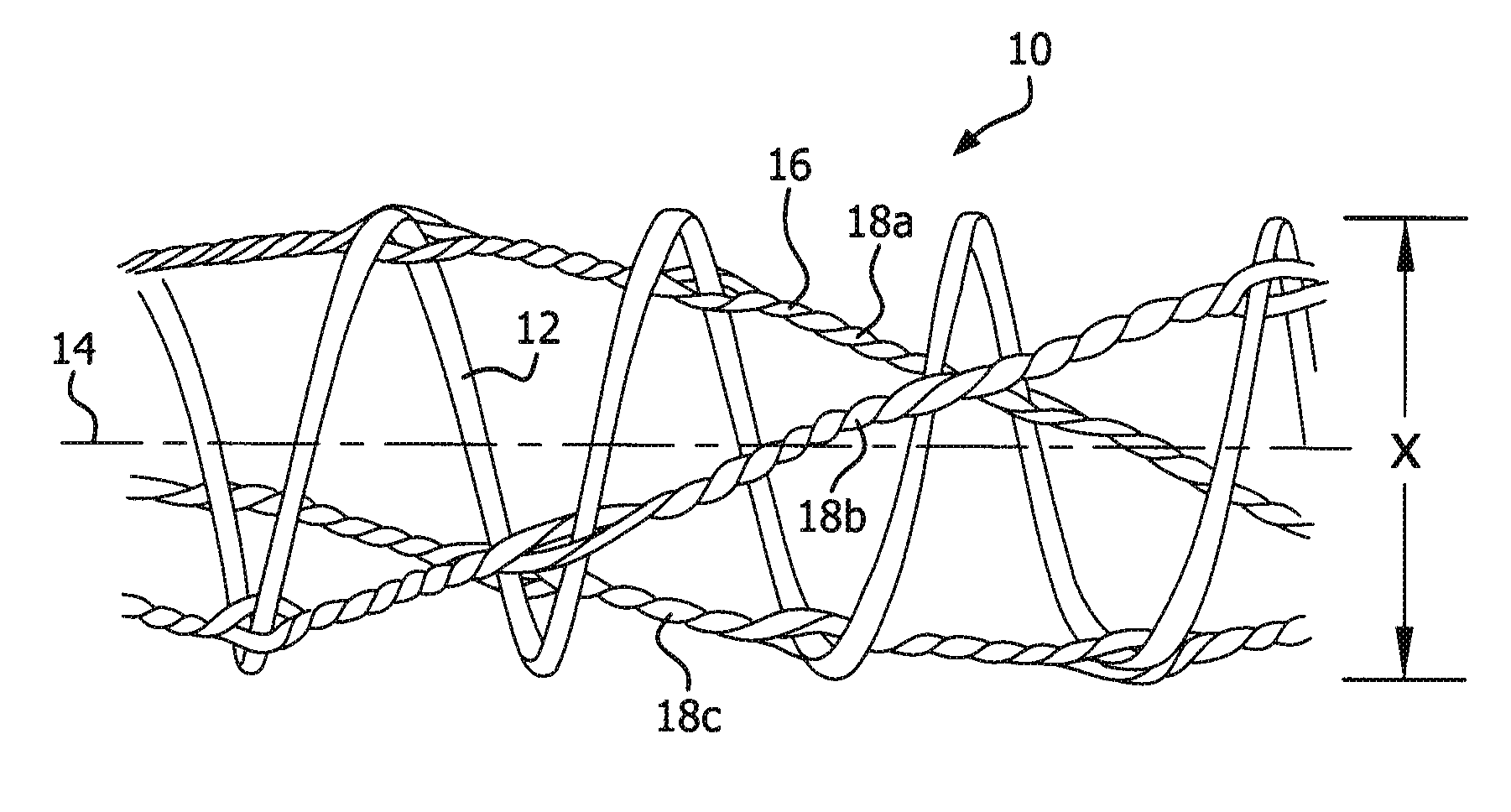
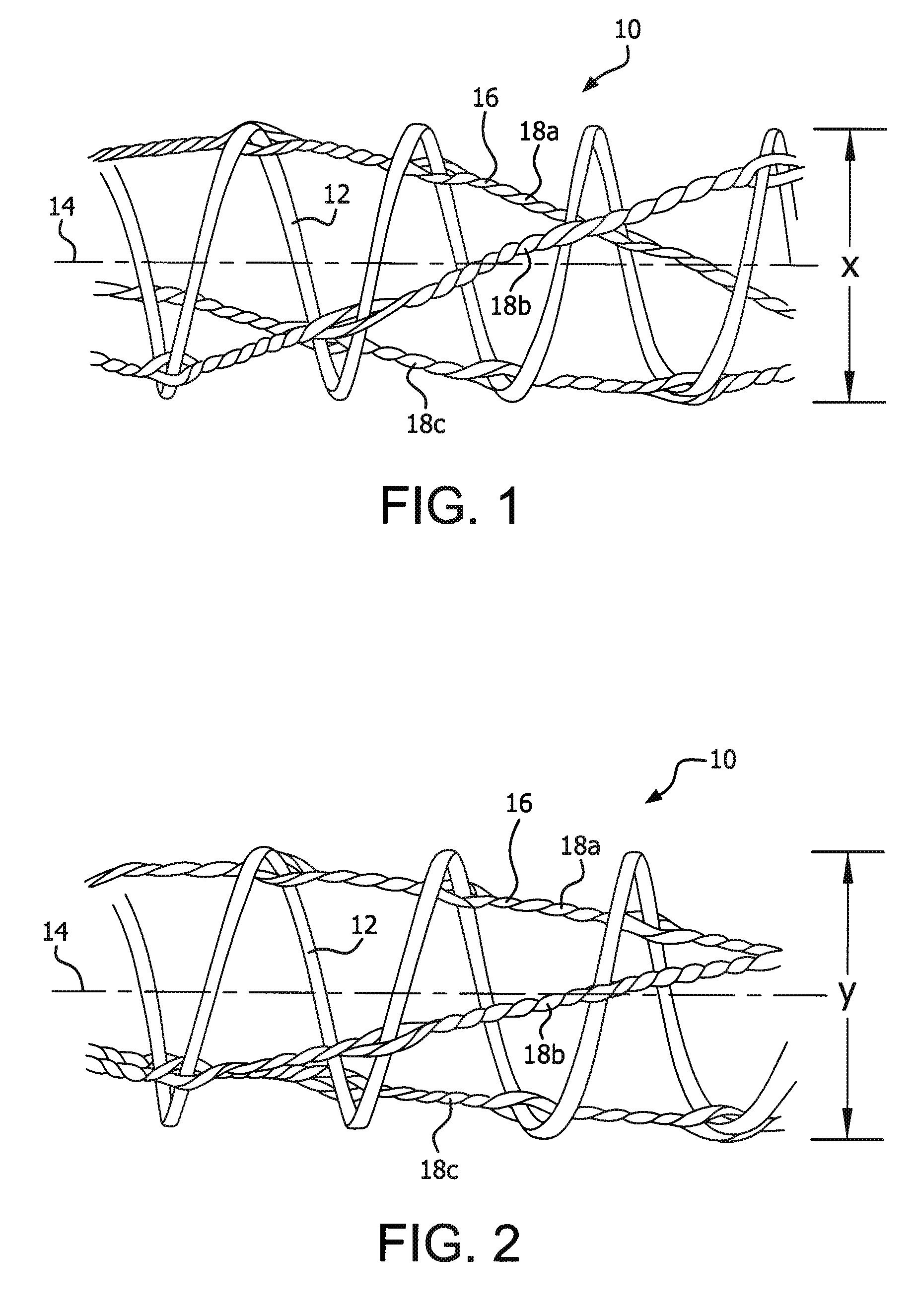
[0066]This Example describes the assembly of an ePTFE tube that can be easily removed from an assembly mandrel. On a 0.136″ steel mandrel a 1″ wide expanded polytetrafluroethylene (ePTFE) film (having longitudinally oriented strength, minimal transverse and shear strength, and with FEP on one side functioning as an adhesive) was wrapped at 40° pitch relative to the mandrel axis in a right handed helix orientation with the FEP facing away from the mandrel. Next, a 0.25″ wide ePTFE film was wrapped at a 74° pitch in a right handed helix orientation over of the first film with the FEP facing toward the mandrel. The assembly was then thermally processed on-mandrel at a temperature of 320° C. for 13 minutes. The tube was easily removed from the mandrel and no necking was observed at loads below material yield strength.

example 2

Uniaxially Oriented ePTFE Film with Polyimide Film

[0067]This Example describes the assembly of an ePTFE tube comprising a non-compliant polyimide film (Kapton®) between the ePTFE layers. On a 0.236″ steel mandrel a 1.0″ wide ePTFE film was wrapped at a 56° pitch relative to the mandrel axis in a right handed helix orientation with the FEP facing away from the mandrel. Next, a 0.050″×0.001″ polyimide film was wrapped at 82° pitch relative to the mandrel axis at a right handed helix orientation over of the first film. Then a 1″ wide ePTFE film was wrapped at a 56° pitch relative to the mandrel axis at a right handed helix orientation on top of the polyimide film with the FEP facing toward the mandrel. The assembly was then thermally processed on-mandrel at a temperature of 320° C. for 13 minutes, after which tube was removed from the mandrel.

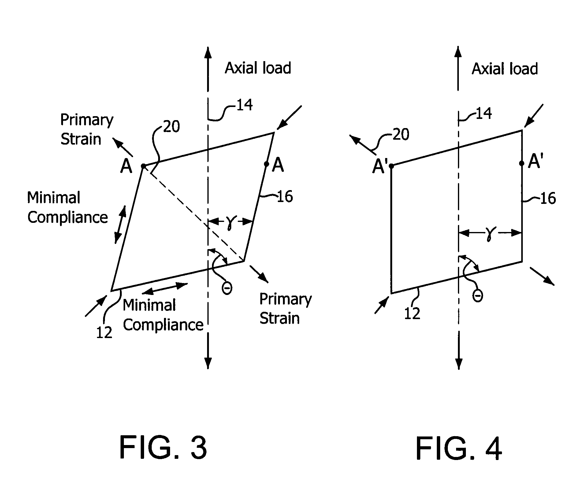
[0068]The non-compliant polyimide film used for high angle wrap limits axial strain and allows the use of a higher angle ePTFE wrap. The higher a...

example 3

Uniaxially Oriented ePTFE Film with Polyimide Film

[0069]To see if the tube made in Example 2 can be modified to reduce necking, slits were created with a knife into the ePTFE in an orientation parallel that of the film structure (56° pitch relative to the mandrel axis), with approximately 0.050″ spacing between the slits. These slits eliminate “off-axis” strength of ePTFE film allowing diametric growth of the polyimide helix under tension without ePTFE necking. Thus, the introduction of these slits eliminates necking.


PUM


Abstract

An improved tubular structure adapted to increase in diameter upon application of axial force is provided. Increase in diameter is achieved by constructing the tube from multiple layers of material that move relative to each other during axial elongation of the tube. The tube of the present invention can be used both to avoid problems in “necking” found in many prior tube devices, and to provide additional benefits that increases in diameter of the tube during axial elongation can provide. As such, the tube of the present invention may be useful as a manufacturing aid, as a deployment sheath (for example, to deliver medical devices), and in other applications that may benefit from easier tubular sheath removal.

Description

BACKGROUND OF THE INVENTION[0001]1. Field of the Invention[0002]The present invention relates to an improved tubular structure with unique properties suitable for a wide array of applications, including use in manufacturing, as apparatus for positioning and deploying medical diagnostic and treatment devices in a body, and in other uses.[0003]2. Discussion of the Related Art[0004]It is a known property of many tubular constructs, such as those made from flexible plastic materials, that the tube will contract in diameter if the tube is elongated longitudinally. This property is commonly referred to as “necking.” Such necking can be problematic in many applications.[0005]For instance, if a plastic wrap is applied over a mandrel in a manufacturing process, pulling on the end of the plastic wrap to remove the wrap from the mandrel will result in the wrap necking down on the mandrel. This often makes it difficult or impossible to slide the plastic wrap off the mandrel, requiring cutting o...

Claims


Application Information

Patent Timeline
Patent Type & Authority Patents(United States)
IPC IPC(8): A61F2/06A61F2/90
CPCA61F2/88A61F2/966A61F2/82A61F2/962A61F2/90A61F2210/0076A61M2025/0024
Inventor SILVERMAN, JAMES D.
Owner WL GORE & ASSOC INC
Why Eureka
Try Eureka