
Semiconductor device with exposed thermal conductivity part

a technology of exposed thermal conductivity and semiconductor devices, which is applied in the direction of semiconductor devices, semiconductor/solid-state device details, electrical devices, etc., can solve the problems of affecting the heat dissipation to the outside of the package, unable to achieve the effect of high integration, and unable to achieve the effect of reducing heat resistance, easy dissipation of heat, and high integration

Inactive Publication Date: 2013-05-14
HITACHI LTD
View PDF11 Cites 0 Cited by
  • Summary
  • Abstract
  • Description
  • Claims
  • Application Information

AI Technical Summary

Benefits of technology

[0007]Prior to the present application, the inventors tried to three-dimensionally stack semiconductor chips using liquid adhesive. However, the liquid adhesive is subject to a load of stacking the semiconductor chips when controlling the thickness of a bonding layer. The thickness easily varies, making it difficult to control the bonding layer thickness and the heat dissipation and achieve heat resistance reduction and miniaturization in consequence of making the package thinner.
[0008]The present invention has been made in consideration of the foregoing. It is therefore an object of the invention to provide a structure capable of heat resistance reduction, miniaturization, and high integration needed for semiconductor packages and contribute to high functionality and miniaturization of electronic devices.

Problems solved by technology

The miniaturization and the high integration are impossible.
Since semiconductor chips are stacked, however, the amount of heat generation per package unit area increases to hamper heat dissipation to the outside of the package.
The SIP of the related art provides no structure enabling all of heat resistance reduction, miniaturization, and high integration needed for semiconductor packages and imposes restrictions on high functionality and miniaturization of electronic devices.
However, the liquid adhesive is subject to a load of stacking the semiconductor chips when controlling the thickness of a bonding layer.
The thickness easily varies, making it difficult to control the bonding layer thickness and the heat dissipation and achieve heat resistance reduction and miniaturization in consequence of making the package thinner.

Method used


Image

  • Semiconductor device with exposed thermal conductivity part
  • Semiconductor device with exposed thermal conductivity part
  • Semiconductor device with exposed thermal conductivity part

Examples


first embodiment

[0035]Embodiments of the present invention will be described in further detail with reference to the accompanying drawings.

[0036]The following description includes multiple embodiments or sections as needed. Unless expressly stated otherwise, the embodiments are not unrelated to each other. One of the embodiments provides modifications, details, or supplements for all or part of the others.

[0037]The embodiments to be described may refer to numeric values including the number of elements or items, quantities, and ranges. The embodiments are not limited to but may be greater or smaller than specific numeric values, unless expressly stated otherwise, or unless the embodiments are limited to specific numeric values in principle.

[0038]Obviously, constituent elements including procedure steps are not necessarily requisite for the embodiments, unless expressly stated otherwise, or unless the elements are requisite in principle.

[0039]The embodiments include those virtually approximate to or...

second embodiment

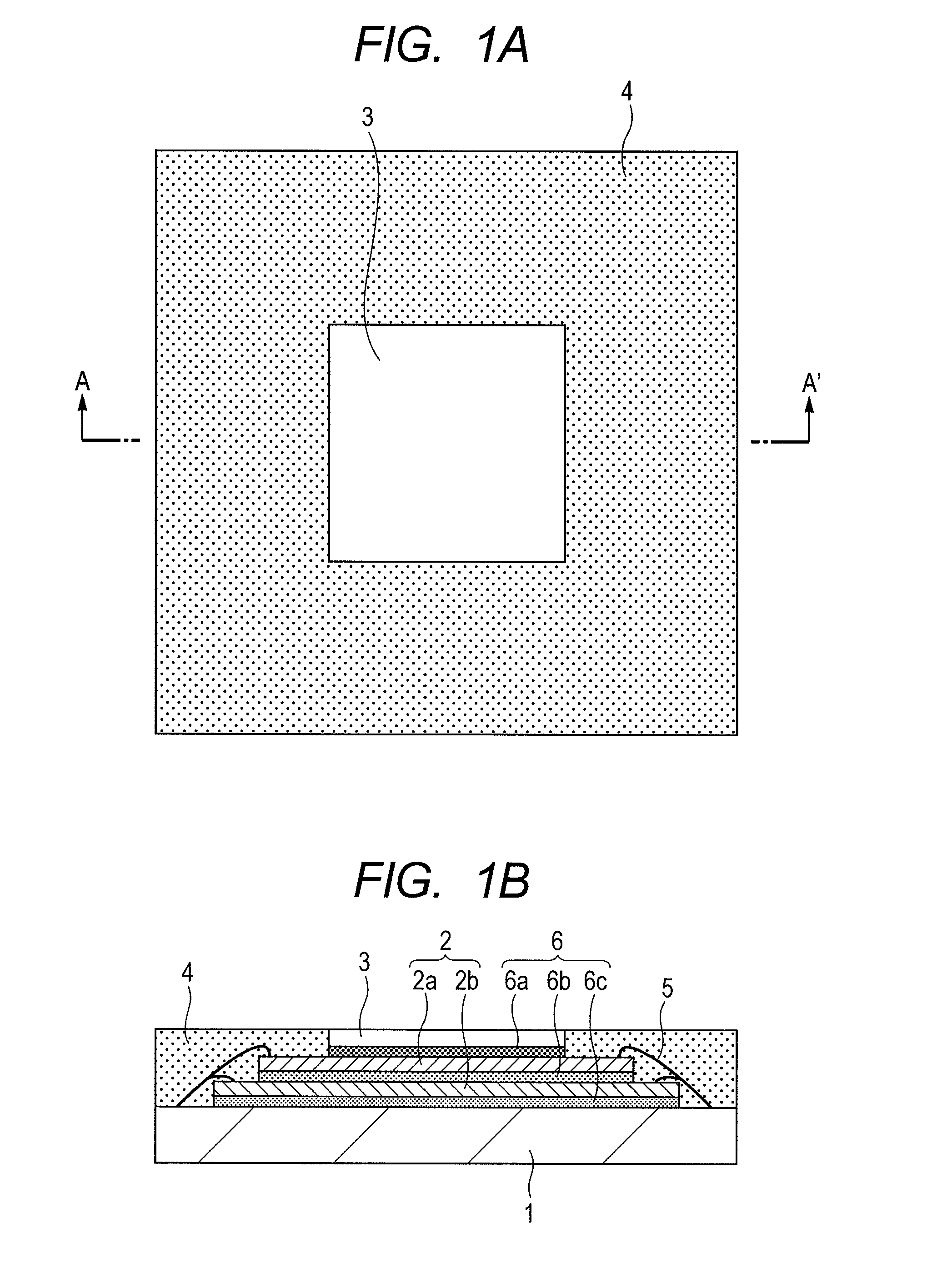
[0080]FIGS. 12A and 12B are a plan view and a cross sectional view illustrating a single-chip package structure without stacked semiconductor chips. FIG. 12B shows section A-A′ of FIG. 12A. Even the single-chip structure is capable of exposing the thermal conductivity part 3 from the surface of the encapsulation resin 4 and hardening the adhesive sheet to form a bonding layer between the thermal conductivity part and the chip and a bonding layer between the semiconductor chip and the wired component. This method is capable of radiation control, heat resistance reduction, and miniaturization of the semiconductor package.

[0081]While there have been described specific preferred embodiments of the present invention, it is to be distinctly understood that the present invention is not limited thereto but may be otherwise variously embodied within the spirit and scope of the invention.

[0082]The present invention is effective for miniaturization, high integration, and heat resistance reduct...


PUM


Abstract

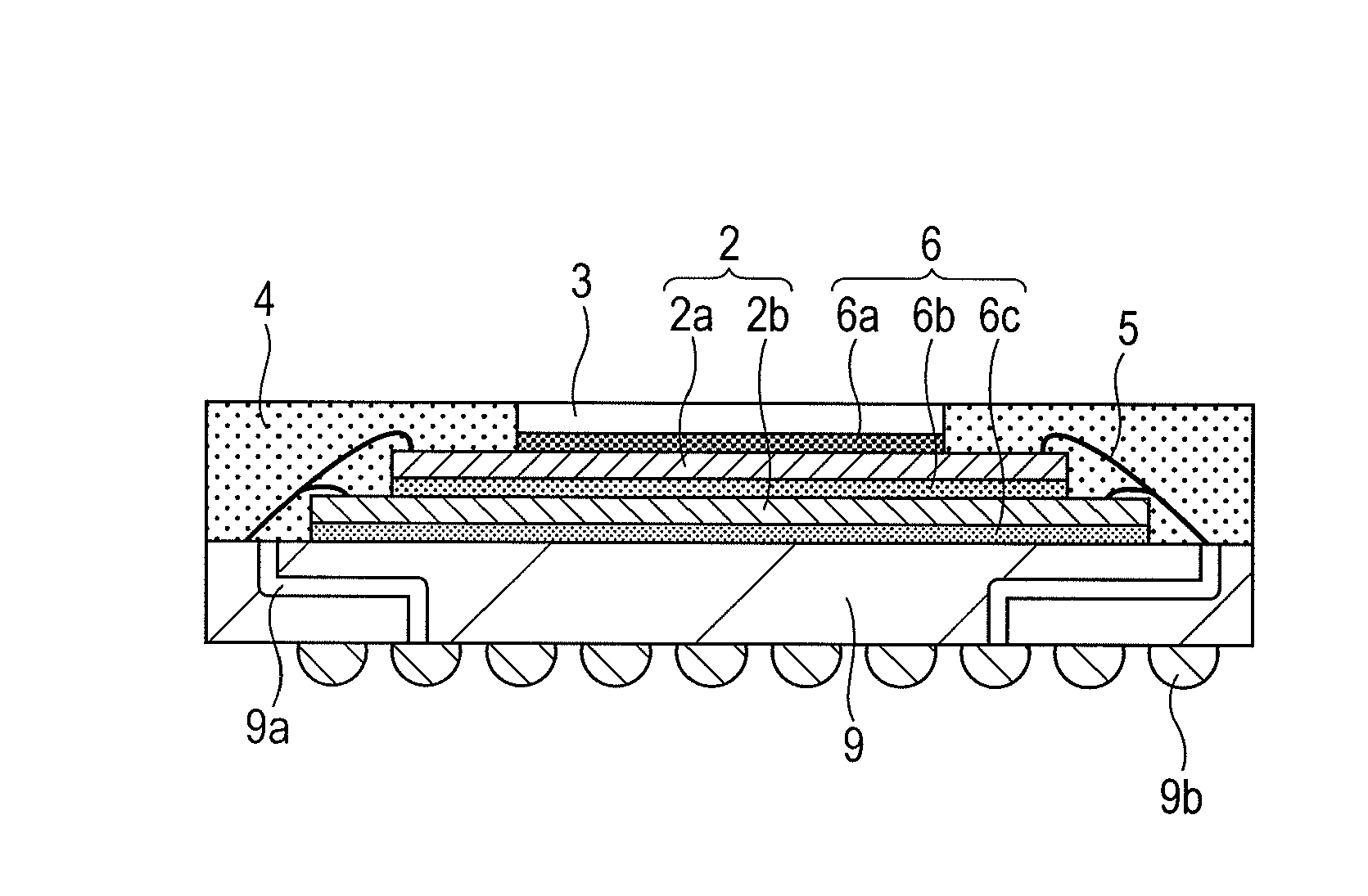
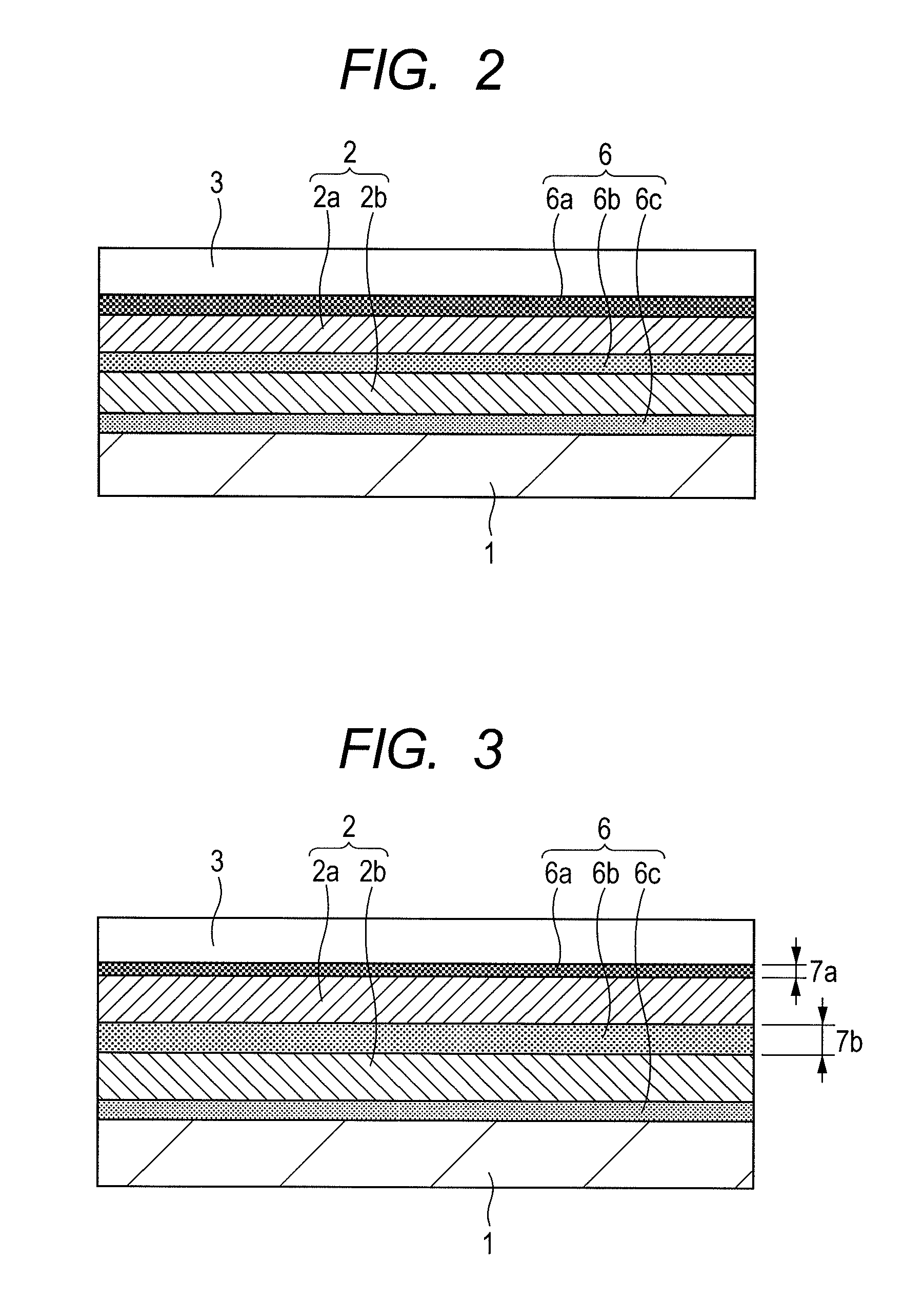
A semiconductor package includes a print circuit part, a lower chip, an upper chip, a thermal conductivity part, and an encapsulation resin. The lower chip and the upper chip are mounted on the print circuit part through wire bonding connection. The thermal conductivity part efficiently dissipates heat from the chips to the outside of the package. The encapsulation resin entirely seals the package while exposing the thermal conductivity part. A adhesive sheet is hardened to form a bonding layer between the thermal conductivity part and the upper chip, a bonding layer between the semiconductor chips, and a bonding layer between the semiconductor chip and the wired component. The configuration contributes to miniaturization, high integration, and heat resistance reduction of a semiconductor package using high-heat-generating ICs.

Description

CLAIM OF PRIORITY[0001]The present application claims priority from Japanese patent application JP 2010-148492 filed on Jun. 30, 2010, the content of which is hereby incorporated by reference into this application.FIELD OF THE INVENTION[0002]The present invention relates to a semiconductor device. More particularly, the invention relates to a technology effective for heat resistance reduction, miniaturization, high integration, and cost reduction of a semiconductor device.BACKGROUND OF THE INVENTION[0003]The system-in-package (SIP) technology is effective for providing highly functional and integrated semiconductor devices. The SIP includes the chip-stacked package technology of stacking semiconductor chips. This structure can highly integrate chips and is used in many fields. For example, see: SATO Toshihiko, Packaging Technology for SiP (System in Package) (<Special Articles> Recent Jisso Technology for SiP and Its Future Trend), Journal of Japan Institute of Electronics Pac...

Claims


Application Information

Patent Timeline
Patent Type & Authority Patents(United States)
IPC IPC(8): H01L23/34
CPCH01L24/83H01L25/0657H01L23/367H01L23/4334H01L2224/48091H01L2224/48227H01L2224/73265H01L2224/838H01L2224/92247H01L2225/0651H01L2225/06568H01L2225/06589H01L2924/01029H01L2924/01082H01L2924/15311H01L2924/00014H01L2924/01033H01L2924/01072H01L2924/014H01L2224/32145H01L2224/32225H01L2924/00H01L2924/1815H01L2924/3512H01L2924/00012H01L2924/10253H01L2924/181H01L24/73H01L2924/14
Inventor MOCHIZUKI, CHIHIROKIKUCHI, HIROSHIKOBAYASHI, YOICHIROSHIMA, YASUO
Owner HITACHI LTD
Learn More