
Apparatus for transforming the aspect ratio of an optical input field based on stacked waveguides

an optical input field and aspect ratio technology, applied in the field of apparatus for transforming the aspect ratio of an optical input field based on stacked waveguides, can solve the problems of reducing collection efficiency, difficult to make the fiber bundle device compact, and difficult to obtain changes in aspect ratios more than a factor of five, etc., to achieve high compactness

Active Publication Date: 2013-05-14
DIABESEN TECH BEIJING CO LTD
View PDF12 Cites 12 Cited by
  • Summary
  • Abstract
  • Description
  • Claims
  • Application Information

AI Technical Summary

Benefits of technology

The present invention is about a device that can change the aspect ratio of an optical input without significantly reducing brightness. The design is also very compact.

Problems solved by technology

Such an arrangement will reduce the collection efficiency by approximately the ratio of the area of the fiber cores to the area of the collection bundle.
In addition, it is difficult to re-arrange the close packed configuration at one end to the nominally linear configuration at the other end in a short length, hence it is difficult to make the fiber bundle devices compact.
It is difficult to obtain changes in aspect ratio of more than a factor of five with this arrangement and it is also very difficult to reduce reflection losses at all surfaces and in all polarizations because the beams can be incident at high angles.
The system is complex, and is not suitable for high numerical aperture applications, and also consumes considerable space.
The difficulty with such concentrators is that the angular distribution of the input radiation is not preserved, with angular divergences in the two planes scaling inversely with geometrical scaling in the two planes.
It is difficult to simultaneously obtain high diffraction efficiency, wide field of view, and high numerical aperture with this design.

Method used


Image

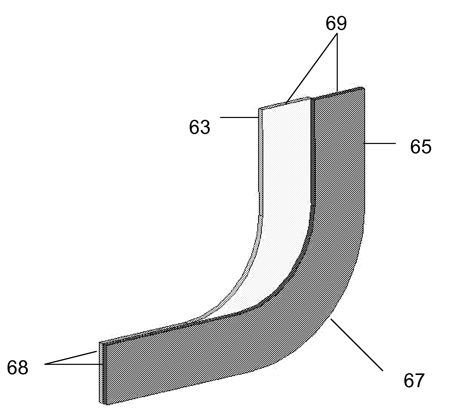
  • Apparatus for transforming the aspect ratio of an optical input field based on stacked waveguides
  • Apparatus for transforming the aspect ratio of an optical input field based on stacked waveguides
  • Apparatus for transforming the aspect ratio of an optical input field based on stacked waveguides

Examples


Embodiment Construction

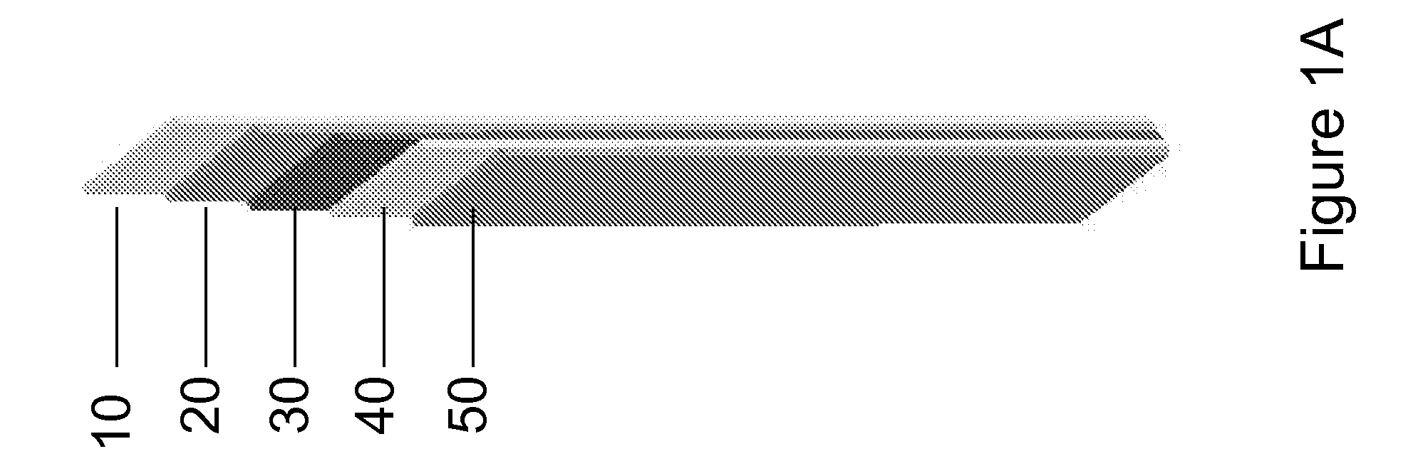
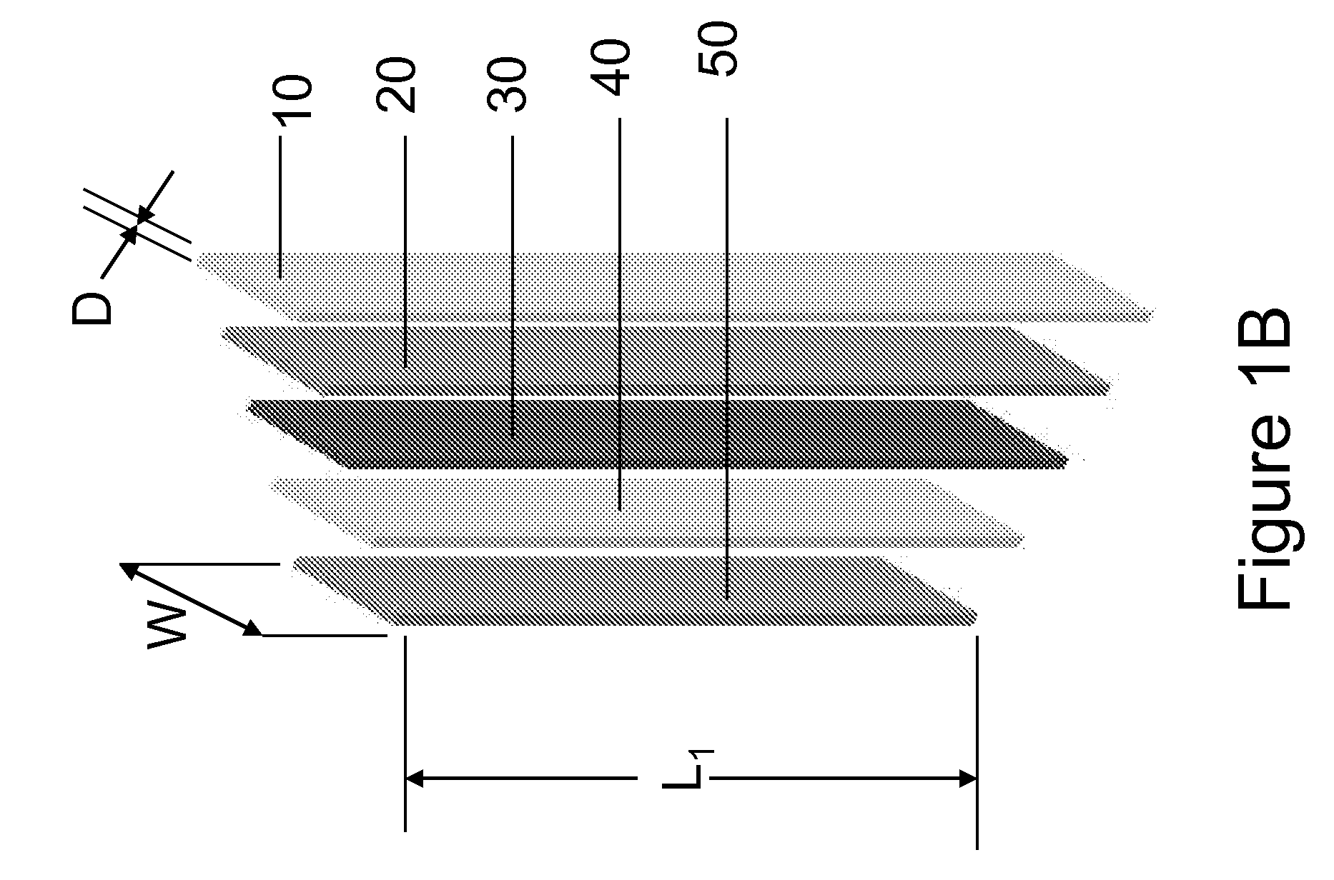
[0020]Referring to FIG. 1A, an isometric drawing of one preferred embodiment is presented. In this example, five rhomboidal shaped slab waveguides 10, 20, 30, 40, and 50 are attached to each other. An exploded view is presented in FIG. 1B, where the width W, the thickness D, and the length, L1, of one waveguides 50 are defined. In this example the waveguides 10, 20, 30, 40, and 50 all have the same widths, W, and thicknesses D. Their lengths are all different, and are defined as L1,2 . . . 5. The difference in lengths between any two contiguous waveguides, Ln−Ln-1, is approximately equal to W, such that each protrudes from its smaller neighbor at the output end by approximately W. In other examples, the volume of any of the slab waveguides is the volume traversed by translating any quadrilateral, including but not limited to a parallelogram or a trapezoid, in a direction perpendicular to the plane of the quadrilateral.

[0021]Two views of a single rhomboid waveguide are presented in F...


PUM


Abstract

An apparatus consisting of stacked slab waveguides whose outputs are vertically staggered is disclosed. At the input to the stacked waveguides, the entrances to each slab lie in approximately the same vertical plane. A spot which is imaged onto the input will be transformed approximately to a set of staggered rectangles at the output, without substantial loss in brightness, which staggered rectangles can serve as a convenient input to a spectroscopic apparatus. A slit mask can be added to spatially filter the outputs so as to present the desired transverse width in the plane of the spectroscopic apparatus parallel to its dispersion.

Description

CROSS-REFERENCE TO RELATED APPLICATION[0001]This application claims priority under 35 U.S.C. §119(e) to U.S. Provisional Patent Application Ser. No. 61 / 184,660, filed Jun. 5, 2009, entitled “Apparatus For Transforming The Aspect Ratio Of An Optical Input Field Based On Stacked Waveguides,” which is incorporated herein by reference in its entirety.BACKGROUND OF THE INVENTION[0002]1. The Field of the Invention[0003]This invention relates to the optical transformation of the shape of a nominally circular object to an object with non-unity aspect ratio without substantial loss of brightness. When the aspect ratio of the output is chosen to be high, the resultant shape is particularly appropriate as an input to a diffraction-grating based spectrometer.[0004]2. Background and Relevant Art[0005]When an object is illuminated with a beam of optical radiation for the purpose of gathering light from the object, the optimum shape of the illumination beam is often nearly circular. If for example...

Claims


Application Information

Patent Timeline
Patent Type & Authority Patents(United States)
IPC IPC(8): G02B6/26
CPCG01J3/0229G01J3/02G02B6/10G02B6/26G01J3/024G01J3/04G01J3/0205G02B27/0994G02B6/0076G02B6/12011G02B6/12016
Inventor HALLSTEIN, SASCHAICE, DONALD A.
Owner DIABESEN TECH BEIJING CO LTD
Learn More