Ignition control device

a control device and ignition control technology, applied in the direction of electric control, machines/engines, instruments, etc., can solve the problems of difficult achieve the effect of effective control of the timing of thermal ignition, less energy, and efficient control

Inactive Publication Date: 2013-05-14
MAGINEERING INC
View PDF9 Cites 3 Cited by
  • Summary
  • Abstract
  • Description
  • Claims
  • Application Information

AI Technical Summary

Benefits of technology

[0022]According to the present invention, since, in a case in which the peak prior to ignition occurs in the combustion region, the timing of thermal ignition of the gaseous mixture can be changed with remarkably less energy during the low-temperature oxidation preparation period than the thermal ignition preparation period, timing of thermal ignition of the gaseous mixture in the combustion region is controlled by increasing the amount of OH radicals in the combustion region during the low-temperature oxidation preparation period. Accordingly, the timing of thermal ignition of the gaseous mixture in the combustion region can be efficiently controlled.
[0023]Furthermore, according to the second aspect of the present invention, since the timing of thermal ignition can be accelerated in accordance with the time period by which the timing, at which the amount of OH radicals in the combustion region is increased during the low-temperature oxidation preparation period, is accelerated, timing of starting control by the radical amount adjusting unit is adjusted during the low-temperature oxidation preparation period in accordance with intended timing of thermal ignition of the gaseous mixture. This means that timing of thermal ignition is accelerated by a time period by which the timing of starting control is accelerated. Accordingly, the actual timing of thermal ignition can be appropriately controlled toward the intended timing of thermal ignition of the gaseous mixture.
[0024]Furthermore, according to the third aspect of the present invention, since the LTO timing is accelerated in accordance with the increased amount of OH radicals in the combustion region during low-temperature oxidation preparation period, the amount of OH radicals to be increased is adjusted in accordance with intended timing of thermal ignition of the gaseous mixture. Accordingly, the actual timing of thermal ignition can be appropriately controlled toward the intended timing of thermal ignition of the gaseous mixture.
[0025]Furthermore, according to the fifth aspect of the present invention, since an enormous amount of energy is required to control the timing of thermal ignition of the gaseous mixture if the peak of the heat release rate does not occur before the gaseous mixture is thermally ignited, the amount of OH radicals in the combustion region is increased by the radical amount adjusting unit only in a case in which the peak of the heat release rate occurs prior to the timing of thermal ignition of the gaseous mixture. Accordingly, it becomes possible to effectively control the timing of thermal ignition of the gaseous mixture in the combustion region.
[0026]Furthermore, according to the seventh aspect of the present invention, OH radicals are generated in a broader area than a plasma forming area in which plasma has been caused only by discharge (plasma forming area before the plasma has expanded). Here, the inventor of the present invention has found that “in order to control the timing of thermal ignition of the gaseous mixture by increasing the amount of OH radicals in the combustion region during the low-temperature oxidation preparation period, it is effective to generate OH radicals in a relatively broader area in the combustion region”. On the other hand, in a case in which plasma is generated merely by discharge, or laser beam is radiated and condensed to the combustion region (see patent document 1), an area in which OH radicals are generated is narrow. According to the seventh aspect of the present invention, the timing of thermal ignition of the gaseous mixture can be controlled more efficiently in comparison to such cases.

Problems solved by technology

However, those ignition methods have a drawback in that it is difficult to control the timing of thermal ignition.

Method used


Image

  • Ignition control device
  • Ignition control device
  • Ignition control device

Examples


embodiment

Effect of Embodiment

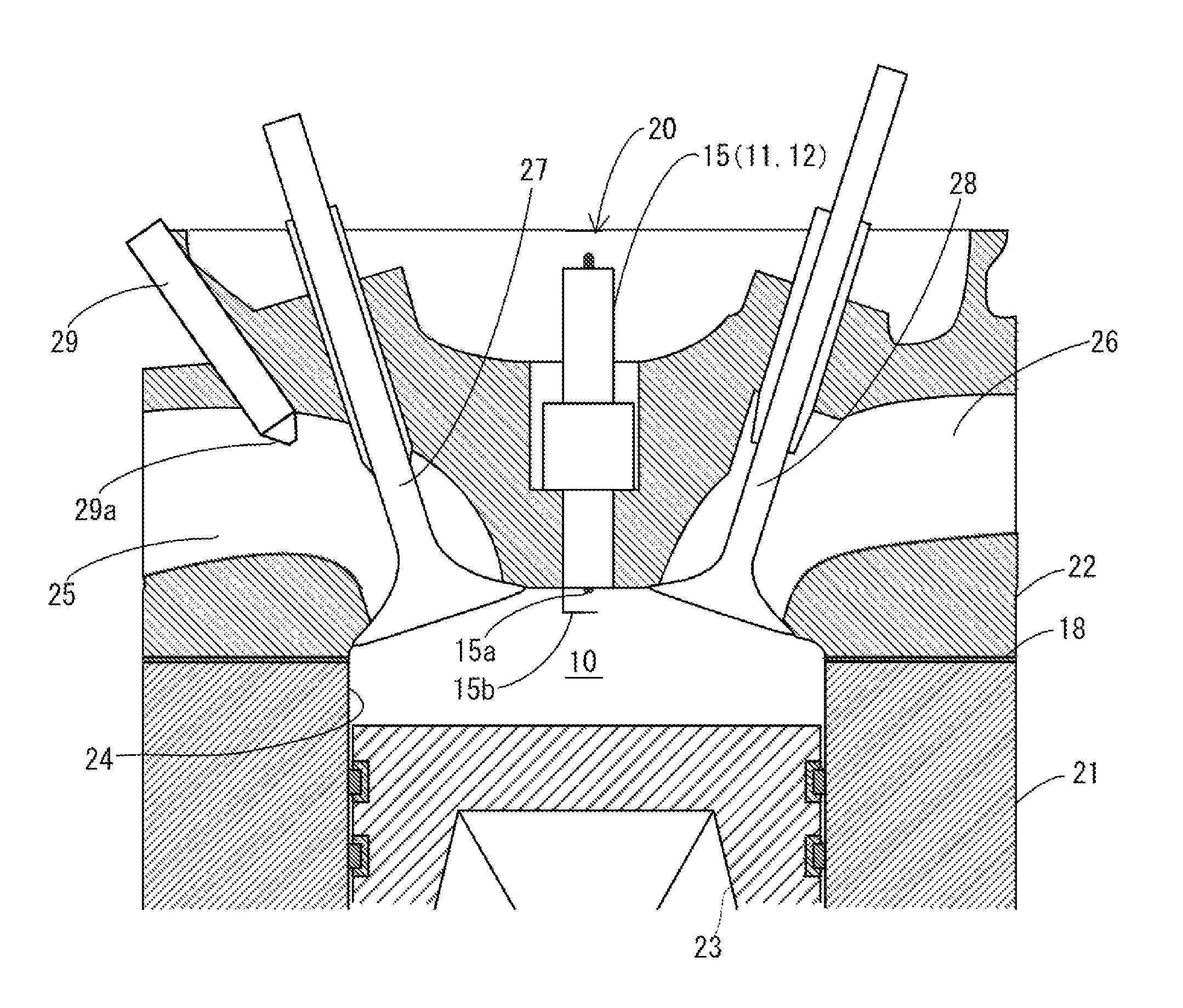
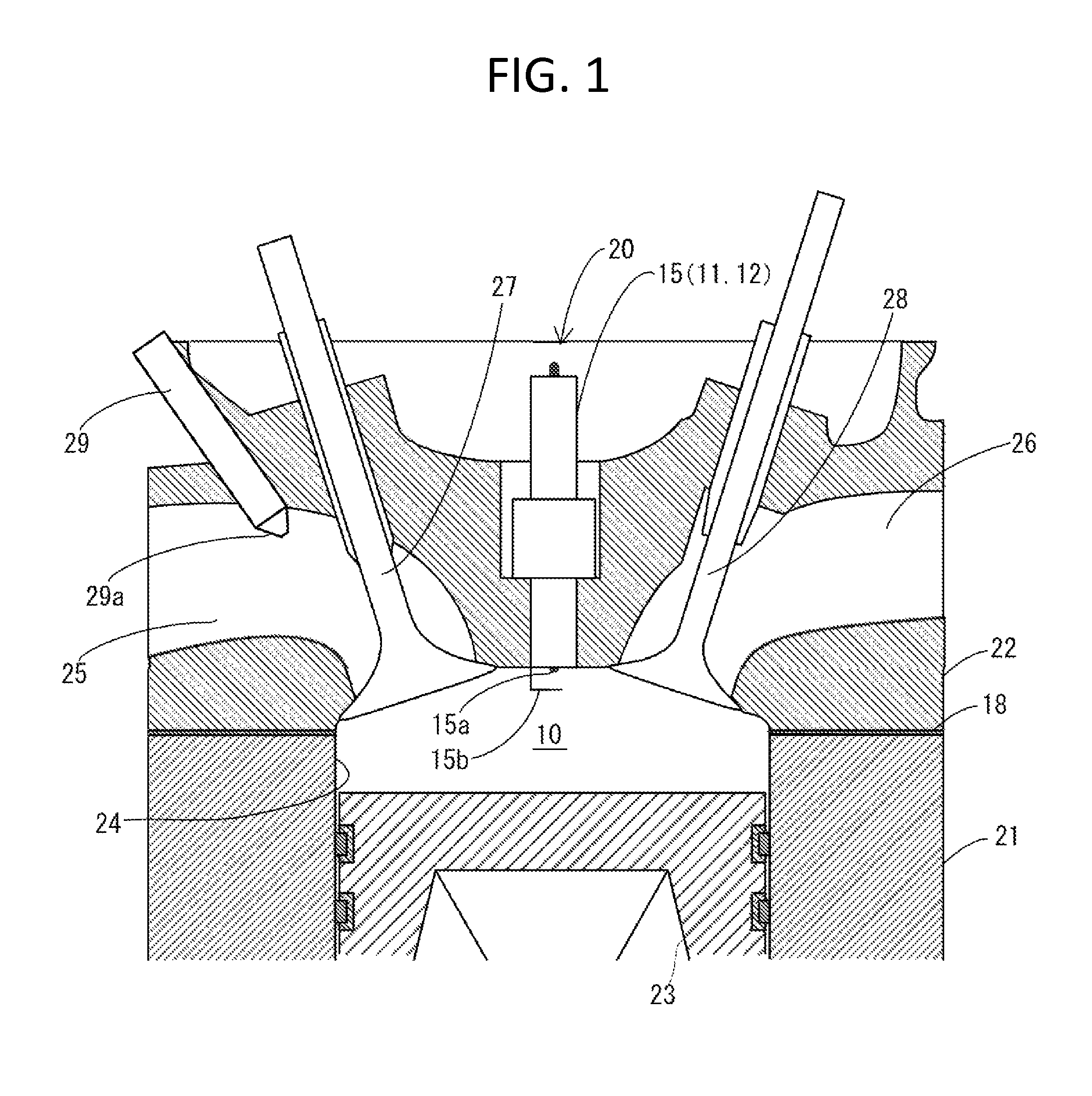
[0066]In the present embodiment, since, in a case in which the peak prior to ignition occurs in the combustion chamber 10, the energy required during the low-temperature oxidation preparation period to change the timing of thermal ignition of the gaseous mixture is remarkably less in comparison to the energy required during the thermal ignition preparation period, the amount of OH radicals in the combustion chamber 10 is increased during the low-temperature oxidation preparation period, thereby the timing of thermal ignition of the gaseous mixture in the combustion chamber 10 is controlled. Accordingly, it becomes possible to efficiently control the timing of thermal ignition of the gaseous mixture in the combustion chamber 10.

[0067]Furthermore, in the present embodiment, since the timing of thermal ignition of the gaseous mixture in the combustion chamber 10 can be efficiently accelerated, large amount of gaseous mixture can be combusted before the gaseous mixtu...

first modified example of embodiment

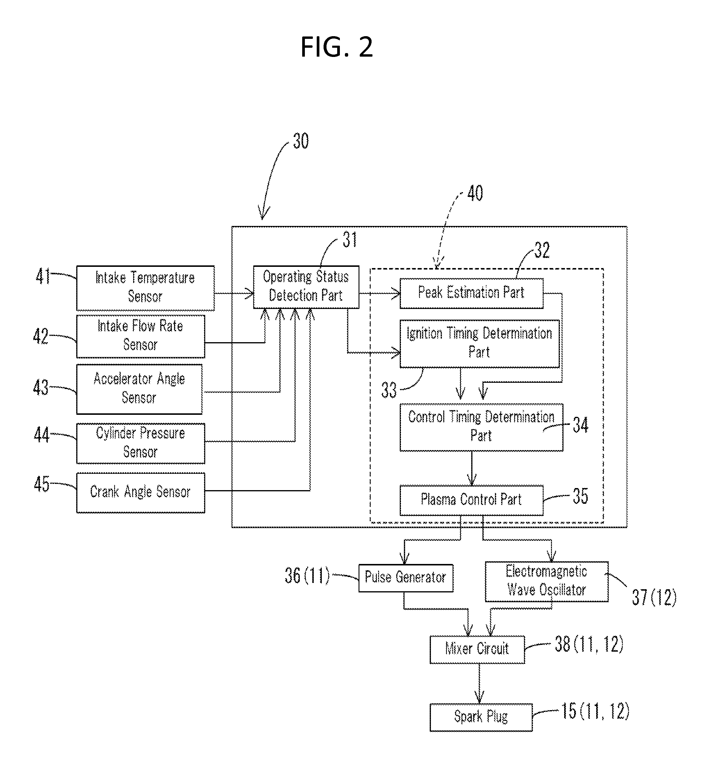
[0070]A first modified example of the present embodiment will be described hereinafter. In the first modified example, the control unit 40 causes the radical amount adjusting units 11 and 12 to adjust the amount of OH radicals to be increased in the combustion chamber 10 during the low-temperature oxidation preparation period in accordance with the intended timing of thermal ignition of the gaseous mixture. In the first modified example, the electromagnetic wave oscillator 37 of the radical amount adjusting units 11 and 12 is controlled so as to increase the increased amount of OH radicals in the combustion chamber 10 in accordance with the degree to which the timing of thermal ignition of the gaseous mixture is accelerated. The electromagnetic wave oscillator 37 is controlled so as to increase the microwave intensity in accordance with the degree to which the timing of thermal ignition of the gaseous mixture is accelerated.

[0071]In the first modified example, since, as described ab...

second modified example of embodiment

[0072]A second modified example of the present embodiment will be described hereinafter. In the second modified example, the control unit 40 causes the radical amount adjusting units 11 and 12 to increase the amount of OH radicals in the combustion chamber 10 only in a case in which the peak prior to ignition occurs. Prior to the estimation operation, the peak estimation part 32 of the control unit 40 performs a determination operation of determining whether or not the peak prior to ignition occurs based on the present operating status of the internal combustion engine 20. The peak estimation part 32 performs the estimation operation only when it has been determined in the determination operation that the peak prior to ignition will occur. If it has been determined in the determination operation that the peak prior to ignition will not occur, the plasma control part 35 does not output the discharge signal nor the radiation signal.

Other Embodiments

[0073]The above described embodiment...


PUM


Abstract

In order to provide an ignition control device 30 which can efficiently control timing of thermal ignition of gaseous mixture in a combustion region 10, the peak estimation part 32, the ignition timing determination part 33, the control timing determination part 34, and the plasma control part 35 control timing of thermal ignition of the gaseous mixture in the combustion region 10 by controlling the pulse generator 36, the electromagnetic wave oscillator 37, the mixer circuit 38, and the spark plug 15 so as to increase the amount of OH radicals in the combustion region 10 during a low-temperature oxidation preparation period that occurs prior to a peak of a heat release rate before the thermal ignition of the gaseous mixture.

Description

TECHNICAL FIELD[0001]The present invention relates to an ignition control device that controls timing of thermal ignition of a gaseous mixture of hydrocarbon and air.BACKGROUND ART[0002]As a method of thermally igniting (self-igniting) a gaseous mixture of hydrocarbon and air, various methods are proposed. For example, for an internal combustion engine, ignition methods such as, for example, a premixed charge compression ignition method and an HCCI (Homogeneous Charge Compression Ignition) method are proposed. Starting premix type combustion as a result of pilot injection or the like in a common rail system of diesel engine belongs to such ignition methods.[0003]For example, as for the internal combustion engine, such ignition methods have drawn attention since those ignition methods can achieve higher heat efficiency than the ignition method with spark ignition, and reduce the emission level of nitrogen oxides (NOx). However, those ignition methods have a drawback in that it is dif...

Claims


Application Information

Patent Timeline
Patent Type & Authority Patents(United States)
IPC IPC(8): F02D41/00
CPCF02D41/3041F02P23/045F02P3/02F02P9/007F02P5/153
Inventor ANDO, HIROMITSUIKEDA, YUJI
Owner MAGINEERING INC
Why Eureka
Try Eureka