Analyte multi-sensor for the detection and identification of analyte and a method of using the same

a multi-sensor and analyte technology, applied in the direction of fluid resistance measurement, instruments, specific gravity measurement, etc., can solve the problems of reducing the stability of the sensor and the gap in technology

Inactive Publication Date: 2013-05-21
SOUTHERN ILLINOIS UNIVERSITY
View PDF27 Cites 36 Cited by
  • Summary
  • Abstract
  • Description
  • Claims
  • Application Information

AI Technical Summary

Benefits of technology

[0007]In another embodiment of the disclosure, a method of detecting and identifying a target in a sample includes exposing a multi-sensor in accordance with the above-described embodiment to a sample comprising or suspected of comprising a target, detecting a change in resistance produced by each of the sensing elements in response to exposure to the sample, creating a response profile from the changes in resistance produced by the at least three sensing elements, and correlating at least a portion of the response profile to a known response profile to identify the target. The presence of the detectable responses corresponds to the presence of the target in the sample and the absence of a detectable response corresponds to the absence of the target in the sample.
[0008]In yet another embodiment of the disclosure, a method of calibrating the multi-sensor in accordance with the above-described embodiment include exposing the multi-sensor to a known analyte or irradiation, detecting a change in resistance produced by each sensing element in response to the known analyte or irradiation; and creating a response profile from the changes in resistance produced by the at least three sensing elements.

Problems solved by technology

The contacts between the grains of conventional granular film sensing elements have propensity to sinter with time and therefore reduce stability of the sensor.
There exists however a technological gap between the laboratory demonstrations using quasi-one-dimensional nanostructures as analyte sensors and a practical electron nose microdevice suitable for up to date, large scale microfabrication and capable of operating in real-world conditions environments.

Method used


Image

  • Analyte multi-sensor for the detection and identification of analyte and a method of using the same
  • Analyte multi-sensor for the detection and identification of analyte and a method of using the same
  • Analyte multi-sensor for the detection and identification of analyte and a method of using the same

Examples


examples

Formation of Tin Oxide Nanowire Mats

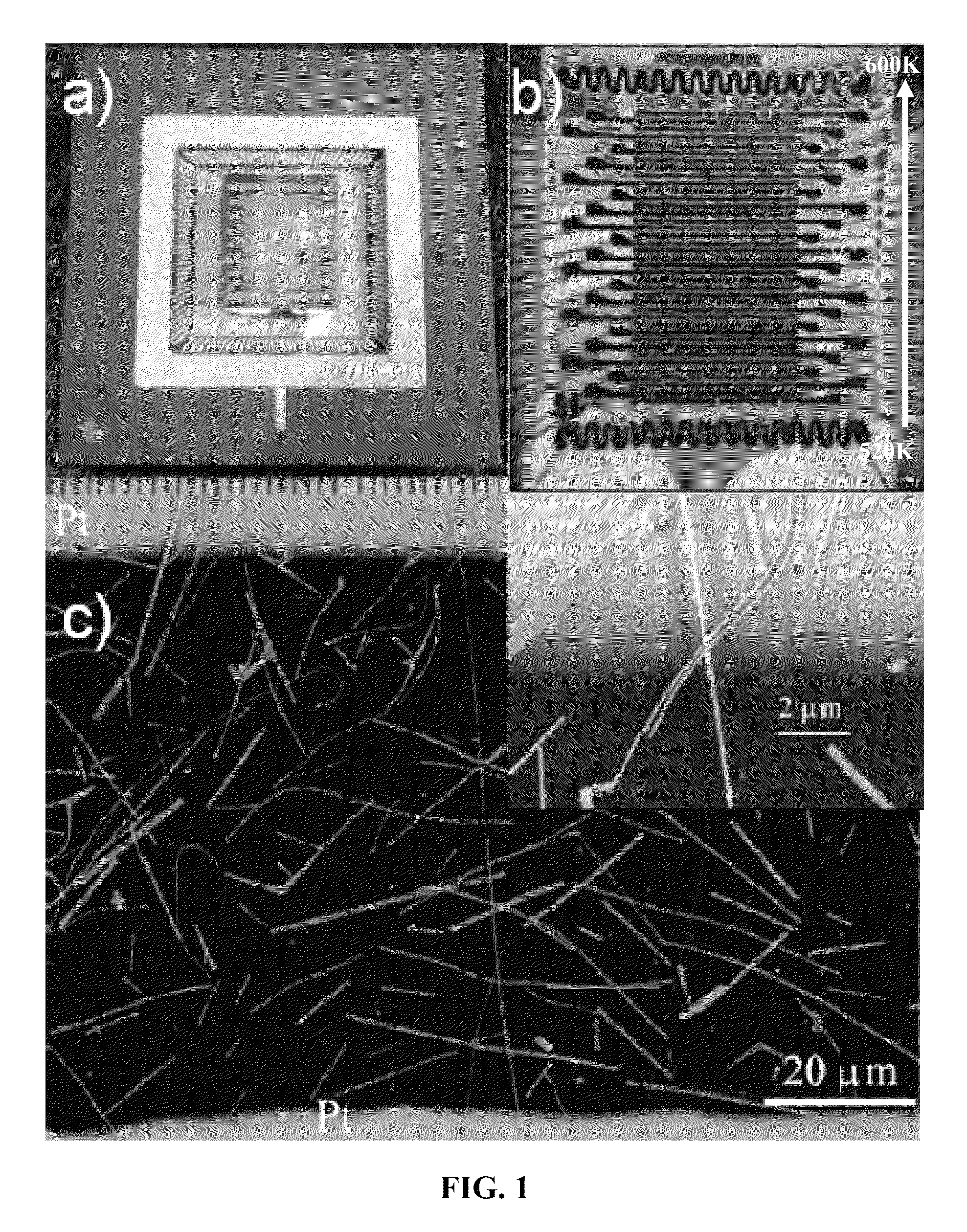
[0067]Referring to FIG. 7, SnO2 nanowire mats were grown using vapor methods (VS) in a quartz tube furnace. SnO (Sigma-Aldrich, 99.99%) was used as a source material and placed in the center of the furnace. The operating temperature was maintained at about 1280 K. The tube was initially pumped to ca 10−2 Torr and further fed with constant Ar (99.995%) flux of 30 sscm rate. The pressure inside the tube was kept at 200 Torr using a needle valve. SnO2 rutile nanowires with the highest densities and length of about a few hundred microns were generally observed in the tube zone where the temperature was in a range of 900 K to 1100 K. The as-synthesized nanowires were then collected and mechanically dry pressed over the surface of a SiO2 / Si KAMINA substrate with 39 pre-deposited Pt electrodes to avoid potential contamination from the lithography protocols. The resultant layer demonstrated excellent adhesion and sufficient thermo-mechanical stability.

[00...


PUM

PropertyMeasurementUnit
diameteraaaaaaaaaa
lengthaaaaaaaaaa
distanceaaaaaaaaaa

Abstract

A multi-sensor as disclosed herein can include a substrate and at least three sensing elements disposed on the substrate. Each sensing element includes two electrodes separated by a distance and a nanowire mat adjacent to and in contact with the electrodes. The nanowire mats include nanowires which define a percolation network. The density of the nanowires in the nanowire mat of one sensing element is different than the density of the nanowires in the nanowire mat of either of the other at least two sensing elements.

Description

FIELD OF THE INVENTION[0001]The disclosure relates to a multi-sensor for the detection and identification of a gas in a sample, and more particularly, to a multi-sensor having a nanowire mat capable of detecting and identifying an analyte or irradiation in a sample.BACKGROUND[0002]A key requirement in the development of analytical sensor systems for industrial, medical, security, and domestic applications is their ability to promptly and reliably detect and recognize a broad range of analytes, often in low concentrations, while working in a continuous mode.[0003]It is well-known that materials or chemical processes release characteristic complex gas ensembles that can be used like a fingerprint for condition monitoring. These complex gas ensembles are generally referred to as odors if perceptible by the human nose. Sensor systems are being designed to mimic the data acquisition principles of mammalian olfactory systems, which allow one to discriminate single gases as well as odor li...

Claims


Application Information

Patent Timeline
Patent Type & Authority Patents(United States)
IPC IPC(8): B82Y15/00B82B1/00G01N27/04G01R27/22G01R35/00
CPCG01N27/127B82Y15/00G01N33/0034
Inventor KOLMAKOV, ANDREISYSOEV, VICTOR V.
Owner SOUTHERN ILLINOIS UNIVERSITY
Why Eureka
Try Eureka