

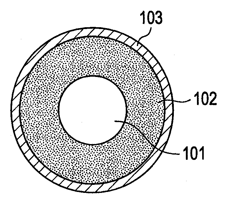
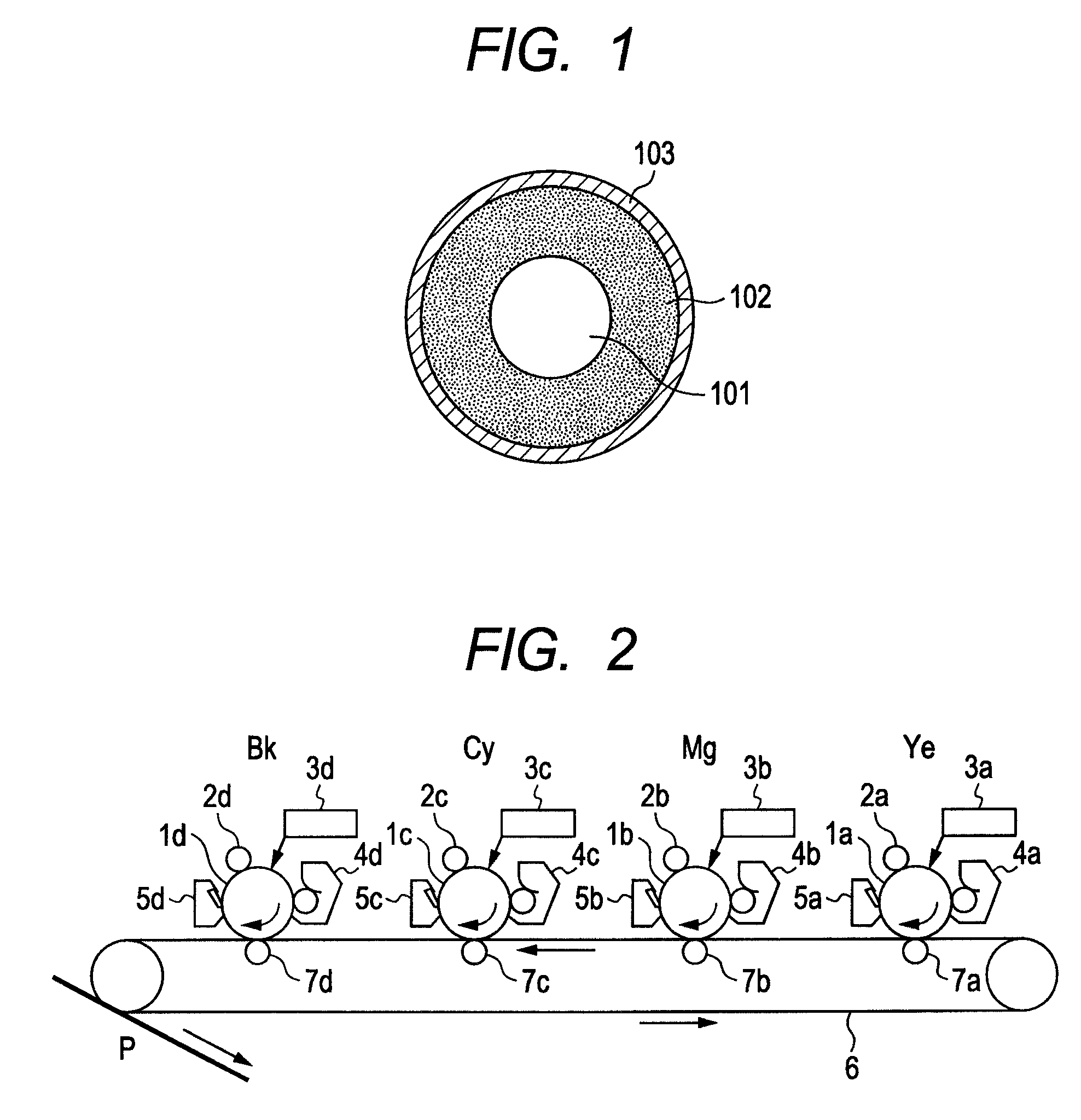
Charging member and process for its production
a charging member and charging process technology, applied in the direction of electrographic process, corona discharge, instruments, etc., can solve the problems of non-uniform charging and streaky defects in electrotrophotographic images, and achieve stable charging performance and low surface free energy
- Summary
- Abstract
- Description
- Claims
- Application Information
AI Technical Summary
Benefits of technology
Problems solved by technology
Method used
Image

Examples
example 1
(1) Formation and Evaluation of Conductive Elastic Layer
[0114]Materials shown in Table 1 were mixed by means of a 6-liter pressure kneader (equipment used: TD6-15MDX; manufactured by Toshin Co., Ltd.) for 24 minutes in a packing of 70 vol. % and at a number of blade revolutions of 30 rpm to obtain an unvulcanized rubber composition. To 174 parts by mass of this unvulcanized rubber composition, 4.5 parts of tetrabenzylthiuram disulfide (trade name: SANCELER TBzTD; available from Sanshin Chemical Industry Co., Ltd.) as a vulcanization accelerator and 1.2 parts of sulfur as a vulcanizing agent were added. Then, these were mixed by means of an open roll of 12 inches in roll diameter at a number of front-roll revolutions of 8 rpm and a number of back-roll revolutions of 10 rpm and at a roll gap of 2 mm, carrying out right and left 20 cuts in total. Thereafter, the roll gap was changed to 0.5 mm to carry out tailing 10 times to obtain a kneaded product 1 for elastic layer.
[0115]
TABLE 1Raw...
examples 2 to 39
Preparation of Condensates 2 to 17
[0165]Condensate intermediates 2 to 9 were prepared in the same way as the condensate intermediate 1 in Example 1 except that their components were formulated as shown in Table 4. Details about symbols EP-1 to EP-5 of the components (A) and (B) and also He and Ph which are noted in Table 4 are shown in Table 6.
[0166]
TABLE 4Con-den-sateSynthesis 1inter-Componentmedi-Component (A)(B)ateEP-1EP-2EP-3EP-4EP-5HePhH2OEtOHNo.(g)(g)(g)(g)(g)(g)(g)(g)(g)111.56————62.11—11.3491.87269.97——————9.6197.26338.35————33.53—10.5394.22411.75————41.0825.6411.5286.645—9.82———64.86—11.8490.156——13.01——59.72—10.993.187———11.93—61.40—11.2192.118————13.6362.11—11.34103.459 5.75—— 6.00—61.76—11.2891.99
[0167]Condensates 2 to 9 were prepared in the same way as the condensate 1 in Example 1 except that their components were formulated as shown in Table 5. About the condensates obtained, they were evaluated in the same way as Evaluation (1) and Evaluation (2) described in Example...
PUM
| Property | Measurement | Unit |
|---|---|---|
| electrical resistance | aaaaa | aaaaa |
| electrical resistance | aaaaa | aaaaa |
| thickness | aaaaa | aaaaa |
Abstract
Description
Claims
Application Information