

Diesel engine having cams for controlling the intake valves, which have a main lobe and an additional lobe radiused to each other
a technology of intake valve and cam, which is applied in the direction of valve drives, non-mechanical valves, instruments, etc., can solve the problems of system insufficient time to ensure an adequate pressure in the chamber, and inefficient system operation in given engine operating conditions
- Summary
- Abstract
- Description
- Claims
- Application Information
AI Technical Summary
Benefits of technology
Problems solved by technology
Method used
Image

Examples
Embodiment Construction
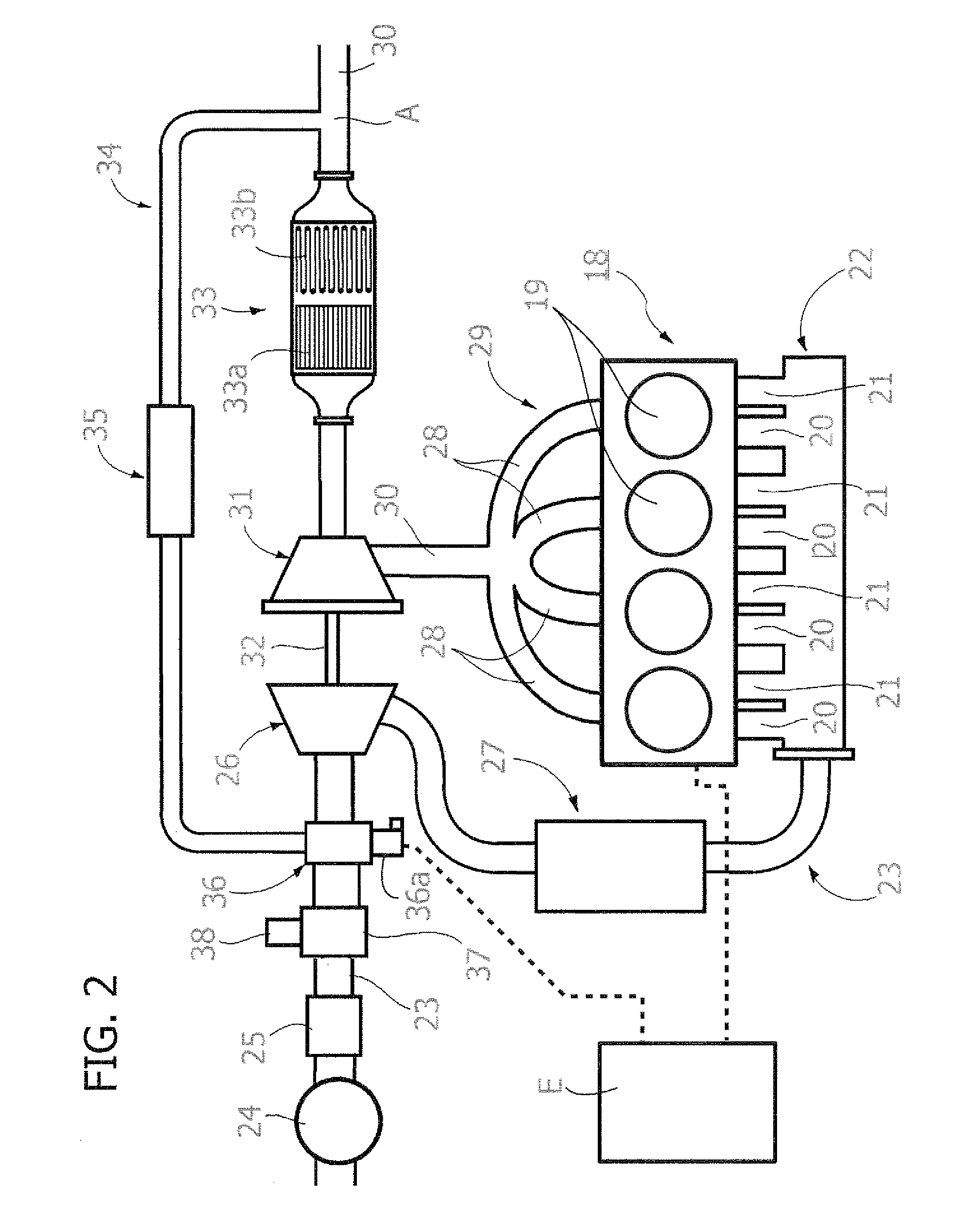
[0023]The present description specifically regards the application of a UNIAIR or MULTIAIR system of the type described above to a diesel engine, preferably a supercharged diesel engine, with external exhaust-gas recirculation (external EGR) of the so-called “long route” type. FIG. 2 of the annexed drawings is a schematic illustration of a preferred embodiment of the diesel engine according to the present invention. As already indicated above, the scheme of FIG. 2 is in itself of a known type. In particular, it has already been proposed by the present applicant (see EP-A-1 589 213) to apply the UNIAIR or MULTIAIR system described above to an engine with the scheme illustrated in FIG. 2. In said figure, the reference number 18 designates as a whole a diesel engine with four cylinders 19, each provided with two intake ducts 20, 21 controlled by respective intake valves (not illustrated) and forming part of an intake manifold 22 that receives air through a main intake duct 23. Set in s...
PUM
 Abstract
Description
Claims
Application Information