Ablation catheter with thermally mediated catheter body for mitigating blood coagulation and creating larger lesion

a catheter body and catheter technology, applied in the field of catheters for human tissue ablation, can solve the problems of increasing the likelihood of thromboembolism, increasing the risk of thromboembolism, and significant patient discomfort, so as to prevent excessive heat buildup within the electrode, increase the surface area of the electrode, and improve the effect of energy dissipation

Active Publication Date: 2013-05-28
ST JUDE MEDICAL ATRIAL FIBRILLATION DIV
View PDF8 Cites 44 Cited by
  • Summary
  • Abstract
  • Description
  • Claims
  • Application Information

AI Technical Summary

Benefits of technology

[0020]It is desirable to prevent excessive heat build up within an electrode without necessarily having to increase the size of the electrode, which can lead to increased energy dissipation. In this regard, the inventors have recognized that it is desirable to increase the surface area of an electrode for convective cooling. However, the inventors have also recognized that an increase in the convective cooling surface area of an electrode need not increase the electrically conductive surface area of the electrode and therefore increase the energy dissipated by the electrode. That is, the inventors have recognized that use of a thermally conductive and electrically isolative heat sink that is in thermal contact with the electrode may provide improved cooling for the electrode without significantly altering the operating parameters of the electrode.
[0021]According to one aspect, an ablation catheter is provided for ablating internal tissue of a patient. The catheter includes a body having a proximal portion and a distal end. The distal end is adapted to be inserted into a body cavity relative to a desired location therein (e.g., within the heart). An ablation electrode is connected relative to the distal end of the catheter for providing ablation energy to patient tissue. A heat sink is in thermal contact with the ablation electrode. The heat sink, although in thermal contact with the ablation electrode, is electrically insulated (e.g., substantially electrically isolated) from the ablation electrode. This allows the heat sink to conduct heat away from the ablation electrode without dissipating electrical energy from the electrode. In this regard, the heat sink may prevent build-up of excess heat within the electrode that may result in blood coagulation and / or tissue charring.
[0026]In another aspect, an ablation electrode is provided that has a portion of the active surface of the electrode covered by an electrically insulative material. This electrically insulative material or electrical insulator prevents dissipation of energy from the electrode to surrounding media (e.g., tissue and / or fluid). In such an arrangement, the size of the electrode may be increased to provide additional convective cooling. The electric insulator may prevent the dissipation of energy from a portion of the outside surface of the electrode and thereby reduce the energy required by the electrode for an ablation procedure. Likewise, additional energy may be available for an ablation procedure.
[0027]In one arrangement, the electrically insulative material is applied to an outside surface of the electrode. Such material may be applied as, for example, a film or wrap (e.g., tape) that may extend over or around a portion of the electrode that is not intended to contact patient tissue. Such an electrically insulative material may be thin enough to permit thermal conductivity from the electrode to surrounding media to maintain a desired temperature within the electrode. In another arrangement, the electrically insulative material may also be thermally conductive to enhance heat transfer from the electrode to surrounding material. In one arrangement, a heat shrink tape may be applied to a proximal portion of an electrode while the distal tip of the electrode remains uncovered such that it may be utilized to apply ablation energy to tissue.

Problems solved by technology

Atrial fibrillation can result in significant patient discomfort and even death because of a number of associated problems, including the following: an irregular heart rate, which causes patient discomfort and anxiety; loss of synchronous atrioventricular contractions, which compromises cardiac hemodynamics, resulting in varying levels of congestive heart failure; and stasis of blood flow, which increases the likelihood of thromboembolism.
While pharmacological treatments are sometimes effective, in some circumstances drug therapy has had only limited effectiveness and is frequently plagued with side effects, such as dizziness, nausea, vision problems, and other difficulties.
Precise positioning of the ablation catheter is especially difficult because of the physiology of the heart, particularly because the heart continues to beat throughout the ablation procedures.
Because of problems associated with the use of DC current, however, radiofrequency (RF) has become the preferred source of energy for ablation procedures.
This rise in tissue temperature also causes a rise in the temperature of blood surrounding the electrode, which often results in the formation of coagulum on the electrode, which reduces the efficiency of the ablation electrode.
That is, the convective heat transfer with the surrounding blood alone may not be efficient enough to maintain the proximal portions of the electrode at a temperature that is below the coagulation temperature of blood.
Further, for longer duration procedures or multiple single location procedures, heat may build-up throughout the electrode, which may result in coagulation for the entire electrode as well as the possibility of tissue charring.
However, such large electrodes also reduce delivered energy density and therefore require increased ablation energy to create a desired lesion as energy is dissipated through the increased surface area to surrounding fluid.
This coagulation problem can be especially significant when linear ablation lesions or tracks are produced because such linear ablation procedures conventionally take more time than ablation procedures ablating only a single location and can result in heat build up within the electrode.

Method used


Image

  • Ablation catheter with thermally mediated catheter body for mitigating blood coagulation and creating larger lesion
  • Ablation catheter with thermally mediated catheter body for mitigating blood coagulation and creating larger lesion
  • Ablation catheter with thermally mediated catheter body for mitigating blood coagulation and creating larger lesion

Examples


Embodiment Construction

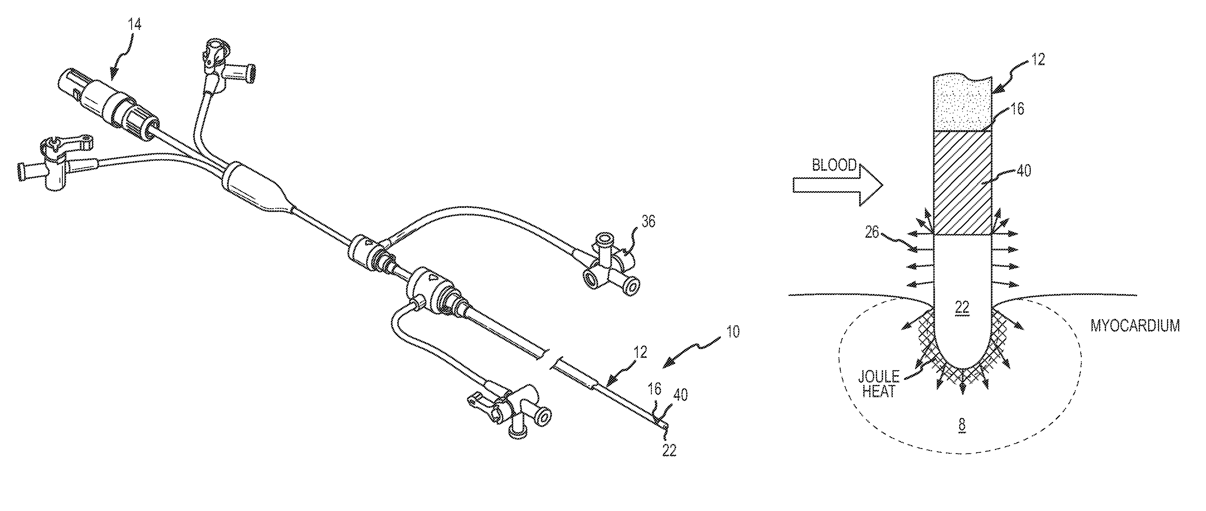
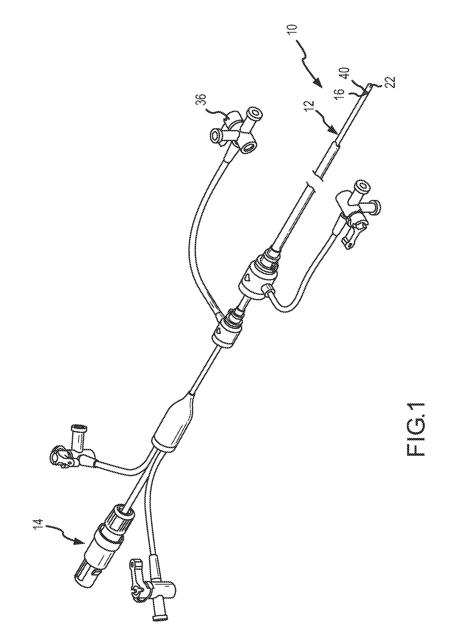
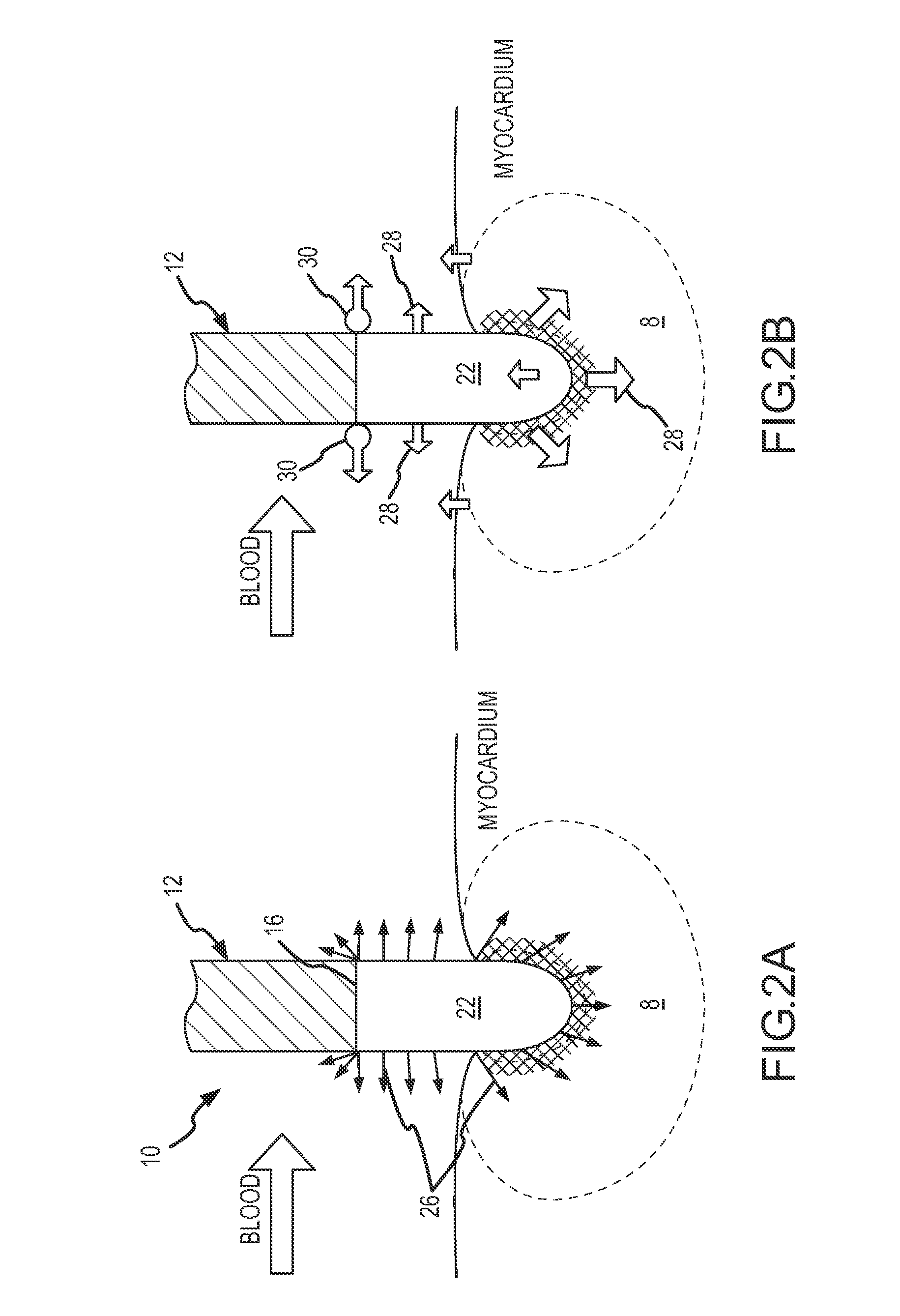
[0043]The ablation catheter 10 of the present invention as shown in FIG. 1 is comprised of a catheter body 12 with a proximal end 14 and a distal end 16, at least one lumen (not shown) extending lengthwise substantially through the catheter body 12, and an electrode (22), secured relative to the distal end 16 of catheter body. In the present embodiment, a heat sink element 40 is disposed between the distal end 16 of the catheter body 12 and the electrode, as will be more fully discussed herein. The catheter body 12 may be a conventional elongated catheter made of materials suitable for use in humans, such as nonconductive polymers. Exemplary polymers used for the production of the catheter body include those well known in the art such as thermoplastic polyurethanes, thermoplastic elastomers (polyamide-based, polyester-based, olefinic and styrenic), polyolefins, nylons, polytetrafluoroethylene, polyvinylidene fluoride, and fluorinated ethylene propylene polymers and other conventiona...


PUM


Abstract

An ablation catheter is provided for ablating internal tissue of a patient. The catheter includes a distal end that is adapted to be inserted into a body cavity relative to a desired location therein (e.g., within the heart). An ablation electrode is connected relative to the distal end of the catheter for providing ablation energy to patient tissue. A heat sink is provided that is in thermal contact with the ablation electrode. The heat sink, in addition to being in thermal contact with the ablation electrode, is electrically isolated from the ablation electrode. This allows the heat sink to conduct heat away from the ablation electrode without dissipating electrical energy from the electrode. In this regard, the heat sink may prevent build-up of excess heat within the electrode that may result in blood coagulation and / or tissue charring.

Description

BACKGROUND OF THE INVENTION[0001]a. Field of the Invention[0002]The invention generally relates to catheters for the ablation of human tissue. One use of such catheters is for ablation of cardiac tissue. More specifically, the invention relates to an ablation catheter including a body having an electrode at a distal end for ablating tissue, as well as a thermally conductive heat sink that conducts heat away from the electrode and surrounding blood to reduce or prevent coagulation of the blood and / or tissue charring.[0003]b. Background Art[0004]Catheters have been in use for medical procedures for many years. Catheters can be used for medical procedures to examine, diagnose, and treat while positioned at a specific location within the body that is otherwise inaccessible without more invasive procedures. During these procedures a catheter is inserted into a vessel near the surface of the body and is guided to a specific location within the body for examination, diagnosis, and treatmen...

Claims


Application Information

Patent Timeline
Patent Type & Authority Patents(United States)
IPC IPC(8): A61B18/18
CPCA61B18/1492A61B2018/00357A61B2018/00005
Inventor CAO, HONGGUO, XIAOPINGSHAI, ISAACYANG, MICHAELBELHE, KEDAR RAVINDRAPAUL, SAURAVTHAO, CHOU
Owner ST JUDE MEDICAL ATRIAL FIBRILLATION DIV
Why Eureka
Try Eureka