Hydrogen and oxygen generator having semi-isolated series cell construction

a technology of hydrogen and oxygen generator and semi-isolated series cell, which is applied in the direction of manufacturing tools, instruments, electric circuits, etc., to achieve the effect of facilitating sealing of the upper edges, minimizing current leakage, and facilitating electrical connections the most easily mad

Inactive Publication Date: 2013-05-28
RICHARDSON DAVID THOMAS
View PDF24 Cites 19 Cited by
  • Summary
  • Abstract
  • Description
  • Claims
  • Application Information

AI Technical Summary

Benefits of technology

[0013]The present invention overcomes the problems encountered in the prior art by providing an electrolyzer assembly for electrolyzing water into a mixture comprising hydrogen gas and oxygen gas. The electrolyzer assembly is adapted to deliver the gaseous mixture to the fuel system of an internal combustion engine that when combusted with the fuel, the efficiency of the engine is improved. The electrolyzer assembly of the present invention includes an electrolysis unit having a plurality of generally evenly-spaced, series-coupled laminar metal plates, which are submersed in electrolyte within a generally fluid-tight case having both a gas outlet and a filler inlet. Each pair of adjacent laminar plates forms an electrolytic cell when a voltage differential exists between them. For a preferred embodiment of the invention, the plates are sealed around the side and lower edges so that electrical current leakage will not occur between plates. Electrolyte level above the plates is minimized by having an electrolyte inlet near the bottom of the case and a gas outlet in the case lid, the gas escape entrance of which is positioned at generally the same level as the top of the plates. Any excess electrolyte will, therefore, escape through the gas outlet, along with electrolytically-generated hydrogen and oxygen gases, and return to the supply tank. As the cavity above the plates is sealed, electrolyte generally cannot rise above the level of the top of the plates. A presently preferred embodiment of the electrolysis unit for a vehicular electrical system of nominal 12 VDC employs at least one plate assembly having six or seven, serially-coupled cells, such that the voltage applied between adjacent plates, for a 12-volt electrical system, is about 2 volts. For a vehicular electrical system of nominal 24 VDC, at least one plate assembly having twelve to fourteen, serially-coupled cells. In any case, the optimum voltage range for electrolyzing water into hydrogen and oxygen gases is about 1.5 to 2.0 VDC per electrolytic cell.
[0017]For 24-volt first embodiment of the invention, the case of the electrolysis unit has four thermoplastic side walls (two of which are grooved), a grooved floor panel continuous with the side walls, and a top panel that is sealed to the tops of the side walls. For second embodiment, the case of the electrolysis unit has two opposed grooved thermoplastic side walls, a grooved floor panel continuous with the side walls, and a top panel. The outermost laminar plates of the electrolysis unit function as a pair of opposed side walls to complete the case enclosure. The edges of both of those two outermost laminar plates are bonded to the side walls, grooved floor and top panel in order to provide a leakproof case. The top panel of the case is equipped with a pair of spaced-apart longitudinal grooves that facilitate sealing of the upper edges of the laminar plates to the top panel. For the latter embodiment electrolysis unit, electrical connections are most easily made to the outermost plates and through the top panel. For a six- to seven-cell unit, a ground electrical connection can be made to one of the outermost panels, and a 12 VDC connection can be made to the other. For a twelve- to fourteen-cell unit, the ground electrical connections can be made to each of the outermost panels, and a 12 VDC connection can be made through the top panel to the centermost plate or plates. A third embodiment electrolysis unit is similar to the first embodiment unit, except that it is a 12-volt unit having seven plates and six cells. A fourth embodiment unit does not have a grooved case, but rather relies on a dielectric screw which passes through a central aperture of each plate. Each adjacent pair of plates has a dielectric washer between them that is fitted to the screw. When the screw is tightened through the plate assembly, the plates assume a generally evenly spaced configuration. These plates are inserted as an assembly into an ungrooved lower case portion. However the lower and side edges of the plates are sealed to the sides and bottom of the case, respectively with a waterproof sealer, such as polyurethane adhesive sealant. The sealer is also preferably used with the embodiments having a grooved lower case portion in order to minimize current leakage between plates. For the fourth embodiment electrolysis unit, the input connections are made through the vertical ends of the lower case portion. Epoxy is used to effectively waterproof the holes in the case ends through which threaded terminals pass.

Problems solved by technology

Although acidic solutions, such as acetic acid, can also function as electrolyte, acids tend to foster corrosion of metal components.

Method used


Image

  • Hydrogen and oxygen generator having semi-isolated series cell construction
  • Hydrogen and oxygen generator having semi-isolated series cell construction
  • Hydrogen and oxygen generator having semi-isolated series cell construction

Examples


first embodiment

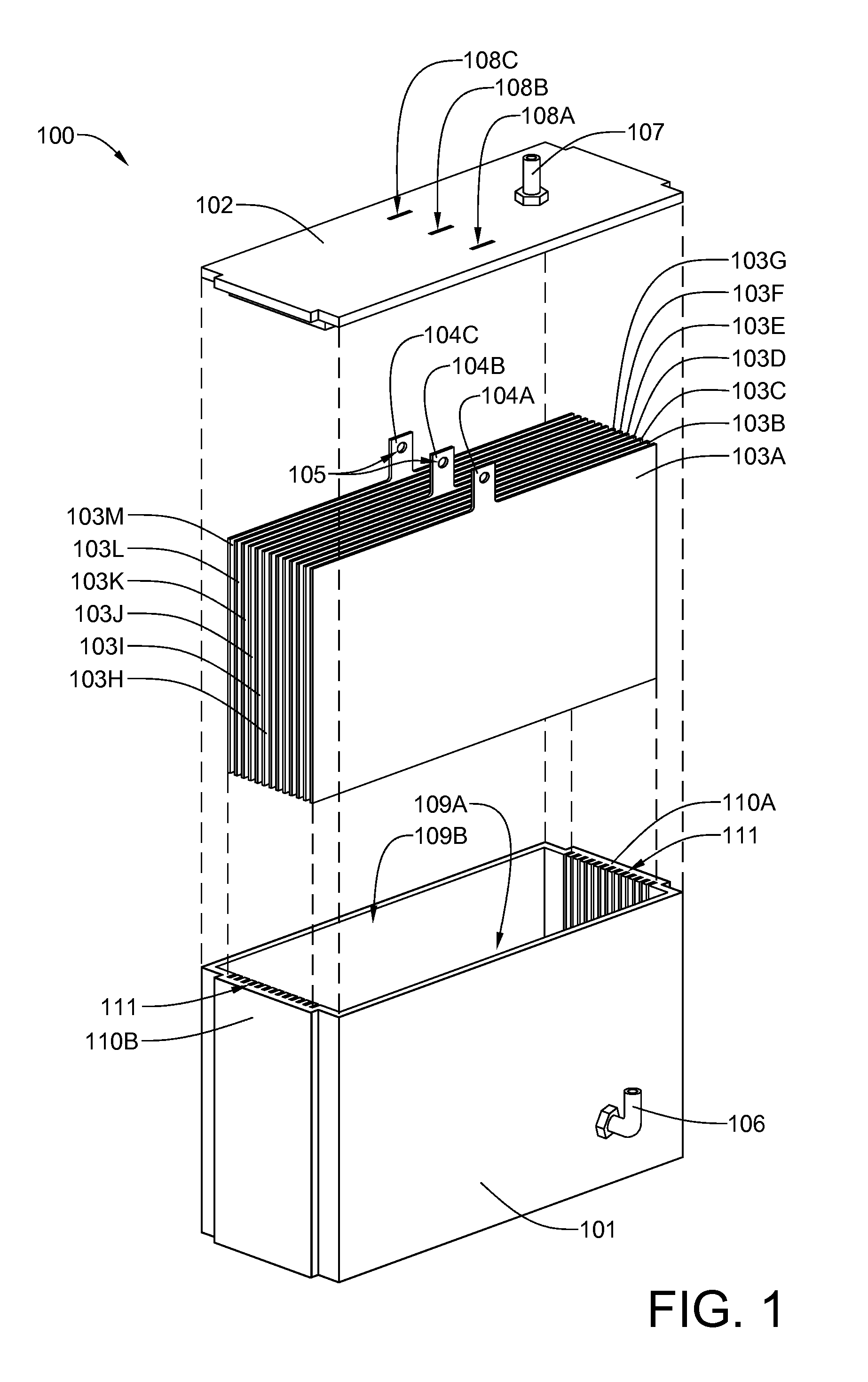
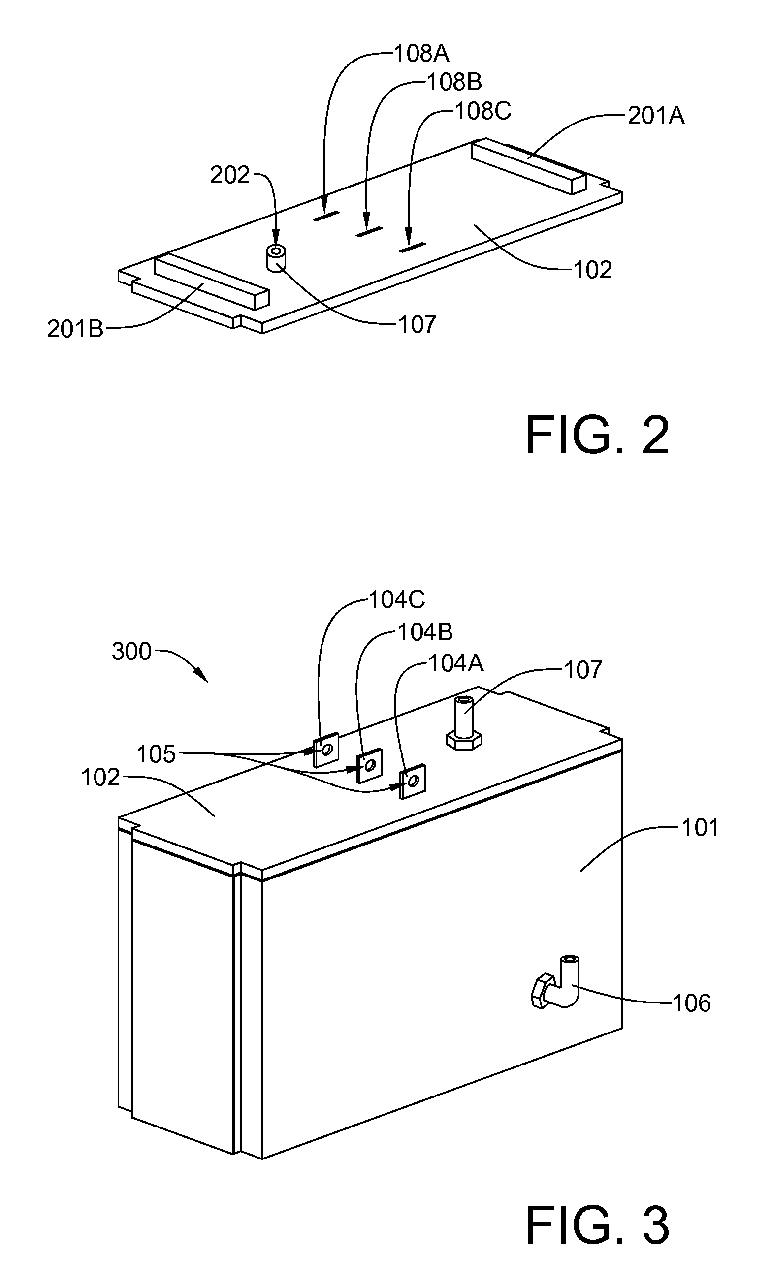
[0032]Referring now to FIG. 1, an exploded first embodiment electrolysis unit 100 includes a case lower portion 101, a case lid 102, thirteen evenly-spaced, parallel laminar plates 103A-103M (103, generally). It will be noted that laminar plates 103A, 103G and 103M each have an electrical connector tab 104A, 104B and 104C, respectively, which extend from an upper central portion thereof. Each of the three connector tabs has an aperture 105 for receiving a threaded fastener that will secure an electrical cable to the connector tab. Laminar plates 103A and 103M will receive a chassis ground connection, while laminar plate 103G will receive a connection to a nominal voltage of 12 VDC. It will be noted that the case lower portion 101 is equipped with an electrolyte inlet 106. It will be further noted that the case lid has a gas outlet 107. It will be further noted that the case lid 102 has three rectangular slits 108A, 108B and 108C, which fit over the three connector tabs 104A, 104B an...

second embodiment

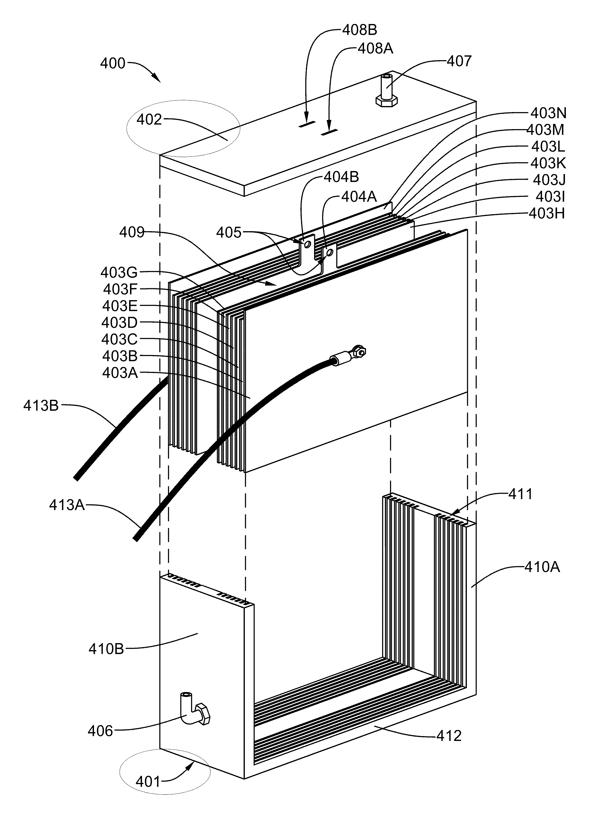
[0037]Referring now to FIG. 6, an assembled second embodiment electrolysis unit 600 has been assembled, with the fourteen laminar plates 403A-403N seated within their respective plate receiving slots within the case lower portion 401, the case lid 402 secured to the case lower portion 401, and the outermost laminar plates 403A and 403N seated and sealed within their respective circumferential grooves, which include their case receiving slots in the case lower portion 401 and the grooves in the case lid 402. A waterproof sealant, such as polyurethane adhesive / sealant may be used successfully to seal the case lid 402 to the case lower portion 401 and to seal the outermost laminar plates 403A and 403N within their respective perimetric grooves. As previously indicated, the partially-exposed laminar plates 403A and 403N will also be connected to chassis ground through conductors 405A and 405B, respectively. Conductor 405A is shown secured to an exposed major surface of laminar plate 403...

fourth embodiment

[0041]Referring now to FIG. 10, a fourth embodiment electrolysis unit 1000 has an ungrooved lower case portion 1001, an ungrooved lid 1002, and an ungrooved case bottom 1003. A dielectric screw 1005 passes through a central aperture of each plate 1004A-1004G. Each adjacent pair of plates has a dielectric washer sandwiched between them that is identical to the dielectric washer 1006 beneath the securing dielectric nut 1007. The dielectric screw 1005 passes through each sandwiched dielectric washer. When the screw 1005 is tightened through the plate assembly 1006, the plates 1004A-1004G assume a generally evenly spaced configuration. These plates are inserted as an assembly into an ungrooved lower case portion. However the lower and side edges of the plates are sealed to the sides and bottom of the case, respectively with a waterproof sealant, such as polyurethane sealant. The sealant is also preferably used with the embodiments having a grooved lower case portion in order to minimize...


PUM

PropertyMeasurementUnit
electromotive forceaaaaaaaaaa
voltageaaaaaaaaaa
voltageaaaaaaaaaa

Abstract

An electrolyzer assembly includes an electrolysis unit having: a hermetically-sealed case made at least partially from a durable dielectric polymer material, the case having a gas outlet and an electrolyte inlet; at least one set of series-coupled, equally-spaced, rectangular, vertically-oriented metal plates installed within the case, each set having first and second end plates, each plate having each side edge sealed to a case wall panel and a bottom edge sealed to the bottom panel; a ground connection to each first end plate; and a voltage connection to each second end plate that is non-zero with respect to the ground connection, thereby providing at least a 1.5 voltage differential between each pair of adjacent plates when gaps between each adjacent pair of plates are filled with electrolyte.

Description

[0001]This application has a priority date based on Provisional Patent Application No. 61 / 096,776, which has a filing date of Sep. 13, 2008, and is titled HYDROGEN AND OXYGEN GENERATOR FOR INTERNAL COMBUSTION ENGINES.BACKGROUND OF THE INVENTION[0002]1. Field of the Invention[0003]The present invention is related to an apparatus and method of improving the fuel efficiency of an internal combustion engine, and in particular, to an apparatus and method for hydrolyzing water into a mixture comprising hydrogen gas and oxygen gas, which is combined with the fuel and air mixture used in an internal combustion engine.[0004]2. History of the Prior Art[0005]During the past 30 years, significant advances have been made in internal combustion engine technology that have dramatically improved the efficiency of internal combustion engines. For gasoline engines, four-valve-per-cylinder combustion chamber designs, coupled with computer monitoring of the combustion process and computer control of bo...

Claims


Application Information

Patent Timeline
Patent Type & Authority Patents(United States)
IPC IPC(8): C25B9/06C25B9/20C25B1/06C25B9/17
CPCC25B1/04C25B9/00Y02E60/366Y02E60/36
Inventor RICHARDSON, DAVID THOMAS
Owner RICHARDSON DAVID THOMAS
Why Eureka
Try Eureka