
Automobile general pressure sensor

a general pressure sensor and automobile technology, applied in the direction of fluid pressure measurement by mechanical elements, instruments, rapid change measurement, etc., can solve the problems of poor vibration resistance, low output sensitivity, low reliability, etc., and achieve the effect of reducing the impact of the outside medium, improving measurement accuracy, and ensuring measurement reliability

Active Publication Date: 2013-06-11
KUNSHAN SHUANGQIAO SENSOR MEASUREMENT CONTROLLING +1
View PDF13 Cites 5 Cited by
  • Summary
  • Abstract
  • Description
  • Claims
  • Application Information

AI Technical Summary

Benefits of technology

The invention describes a new sensor design for automotive pressure measurements. The technical effect is that the silicon piezoresistive sensitive element has a Wheatstone bridge on its front surface and a pressure bearing surface on its rear surface, reducing the impact of external pressure. The sensor is fixed to a housing with a glass ring sheet and a sensor core seat, which is then fixed to the pressure inlet of the housing. The sensor is sealed from external media using multiple measures, ensuring reliable measurements. An insulation oxidation layer is formed on the glass ring sheet and the silicon piezoresistive sensitive element to improve measuring accuracy, and various signal conditioning circuits are introduced for zero-position and full-scale output conditioning, sensitivity temperature coefficient compensation, and non-linear trimming. This design meets the requirements for high-pressure automotive pressure measurements.

Problems solved by technology

However, due to its high brittleness, ceramic materials are poor in resistance to overload of liquid pressure impact (generally with a overload capacity of only 1.5˜2 times of static pressure), and poor in vibration resistance, low in reliability and low in output sensitivity (2 mV / V), so that it is confronted with elimination as it could not meet the development needs of the pressure measurement in automobiles.
However, since the structural principle of the sensor used an adhesive metal strain technology, the fatigue of the organic adhesive resulted in a shorter lifetime of the whole sensor, and measuring accuracy degraded with the time of usage due to creep of the adhesive, and meanwhile, the sensitivity output was still very low.
However, in the glass powder sintering process, the area is relatively large due to the thinness of the glass powder layer, for a glass material which is relatively fragile, when it is subjected to rapid pressure overload impact and temperature impact, rupture will occur in the sintered glass layer, and its pressure overload impact resistance generally still remains only two times, and the operating temperature range is only −20˜80° C., thus it can not meet operating requirements of the automobile level in many aspects.
Also, at the later stage, the disadvantage of above described strain mode was solved by sputter thin film mode general pressure sensor which is derived from the strain mode.
The operating temperature region could also meet requirements of the automobile level, and the sensitivity output could reach 5 mV / V and the resistance of impact pressure overloads two times. However, due to its relatively high manufacturing cost, it can not be popularized in automotive application in a wide range.
Thus the manufacturing cost of the products is increased significantly, and therefore it can not be popularized in automotive applications in a wide range.

Method used


Image

  • Automobile general pressure sensor
  • Automobile general pressure sensor
  • Automobile general pressure sensor

Examples


Embodiment Construction

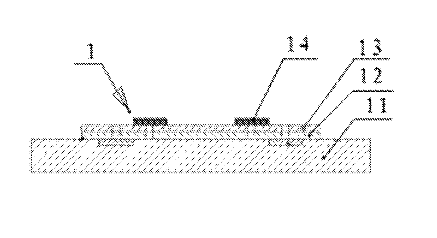
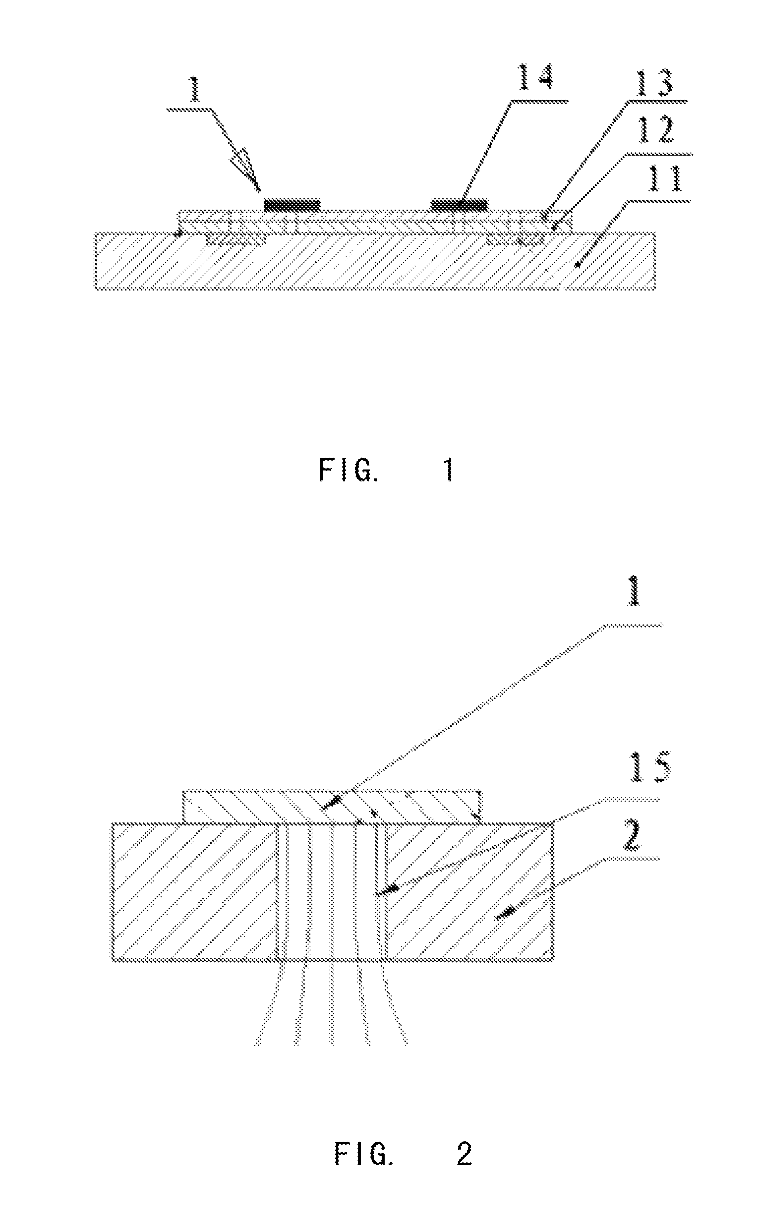
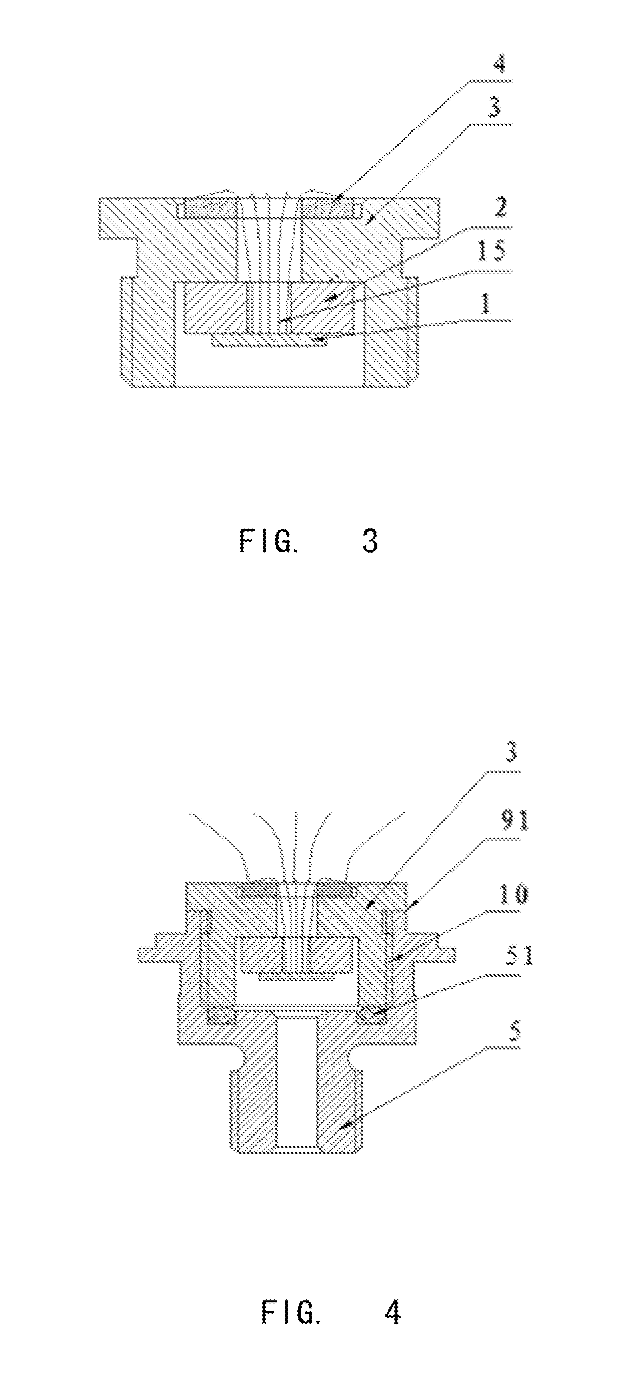
[0046]A further description of the embodiments of the invention will be given in conjunction with FIGS. 1, 2, 3, 4, and 5 respectively in the followings.

[0047]An automobile general pressure sensor comprises a sensor housing, a silicon piezoresistive sensitive core, a sensor core seat, a signal conditioning circuit and an automobile electric device interface. The silicon piezoresistive sensitive core, sensor core seat and signal conditioning circuit are disposed in the inner cavity of the sensor housing. The sensor housing is installed to the automobile electric device interface, and the signal conditioning circuit board 101 provided with the signal conditioning circuit is fixed to the inner cavity of the sensor.

[0048]As shown in FIG. 1 and FIG. 2, the silicon piezoresistive core is composed of piezoresistive sensitive element 1 and glass ring sheet 2. The piezoresistive sensitive element 1 includes a round-shape and flat silicon film 11 the front surface of which is, in turn, covere...


PUM

PropertyMeasurementUnit
pressureaaaaaaaaaa
thicknessaaaaaaaaaa
thicknessaaaaaaaaaa

Abstract

A general pressure sensor for an automobile comprising a sensor shell, a silicon piezoresistive sensitive core, a sensor core seat, a signal conditioning circuit, and an automobile electric device interface is disclosed. The silicon piezoresistive sensitive core, the sensor core seat and the signal conditioning circuit are disposed in the inner cavity of the sensor housing. The sensor housing is installed to the automobile electric device interface, and the silicon piezoresistive sensitive core comprises a silicon piezoresistive sensitive element and a glass ring sheet. The silicon piezoresistive sensitive element is welded and fixed to a surface of the glass ring sheet. An insulation oxidation layer is formed on one surface of the glass ring sheet and the silicon piezoresistive sensitive element. The other surface of the glass ring sheet is hermetically fixed to the ring-shape recession surface provided on the sensor core seat. The sensor core seat is hermetically and rotationally fixed to a pressure inlet on the sensor housing, after the inner lead wire on the silicon piezoresistive sensitive core is led to an interposing board provided on one end of the central hole through the other end of the central hole on the ring-shape recession surface of the sensor core seat, and then is led out by the automobile electric device interface via the signal conditioning circuit.

Description

PRIORITY CLAIM[0001]This application claims priority under 35 U.S.C. 119 to Chinese Patent Application No. 201010187894.1, filed May 31, 2010, which is incorporated herein by reference.FIELD OF THE INVENTION[0002]This invention relates to a general pressure sensor for an automobile, and more particularly, relates to a general pressure sensor for an automobile based on silicon-based MEMS technology. The sensor can be used for pressure measurement for media such as oil pressure, gas pressure, fuel, refrigerant, liquid pressure and the like in various automobiles and respective vehicle systems.BACKGROUND[0003]As one of the information sources of an automotive electronic control system, the general purpose pressure sensor for an automobile is a critical part of the automotive electronic control system, and also is one of the core contents of the research on the technical field of automotive electronics. The general pressure sensors for an automobile are mainly used for the control of pr...

Claims


Application Information

Patent Timeline
Patent Type & Authority Patents(United States)
IPC IPC(8): G01L9/06
CPCG01L9/0055G01L19/147G01L19/143G01L9/06G01L23/18
Inventor WANG, WENXIANGWANG, BINGMAO, CHAOMINSHI, QIAOLI, WEIWANG, CHAO
Owner KUNSHAN SHUANGQIAO SENSOR MEASUREMENT CONTROLLING
Learn More