Tracking heat flux sensors for concentrating solar applications

a technology of heat flux sensor and concentrating solar energy, which is applied in the direction of heat measurement, instruments, optical radiation measurement, etc., can solve the problems of tracking errors, differences between the measured and actual sun position relative to the collector/receiver axis, and tracking errors, so as to maximize the centering potential of the method

Active Publication Date: 2013-06-11
NAT TECH & ENG SOLUTIONS OF SANDIA LLC
View PDF29 Cites 12 Cited by
  • Summary
  • Abstract
  • Description
  • Claims
  • Application Information

AI Technical Summary

Benefits of technology

[0007]The present invention relates to the use of innovative tracking heat flux sensors located at or near the solar collector's focus for centering the concentrated image on a receiver assembly. With flux sensors mounted near a receiver's aperture, the flux gradient near the focus of a dish or trough collector can be used to precisely position the focused solar flux on the receiver. When mounted in pairs on opposite sides of the focal point, near the edges of the focus even small variations in the position of the focus relative to the flux sensors will cause the flux intensity on one sensor to increase and the other to decrease. This difference in the sensors' signal intensity is used to adjust tracking. Because the gradient of the concentrated flux distribution is greater at the focus, locating the sensors at or near the focal plane maximizes the centering potential of the method.
[0010]It is therefore a primary object of the present invention to provide a tracking heat flux sensor which will respond accurately to solar tracking of point focus dish and line focus trough solar collectors.
[0011]It is another object of the present invention to provide a tracking heat flux sensor that responds sufficiently fast to enable rapid and graceful transitions between open and closed-loop tracking.
[0012]It is a further object of the present invention to provide a tracking heat flux sensor that is low cost to manufacture and install.
[0013]It is still another object of the present invention to provide a tracking heat flux sensor and methodology that is reliable and durable.

Problems solved by technology

However, systematic errors or the failure to accurately position the collector relative to the earth-sun coordinates can result in tracking errors.
Misalignments between the sensor and collector axis causes one of the sensors to be illuminated more than the other, resulting in an error signal that is used to correct the tracking error.
Misalignment of the sun sensor, or deflections of the structure, can lead to differences between the measured and actual sun position relative to the collector / receiver axis.
In addition, unequal distribution of dirt, or unequal response characteristics of the sensors can lead to tracking errors.
The slow response can cause unstable control.
They can also overheat or melt if not adequately thermally coupled to a heat sink.
The competing requirements of fast temperature response vs. having adequate thermal mass to avoid overheating make accurate and responsive closed-loop tracking with thermocouples difficult.
In addition, wind-driven convective heating from a thermal receiver can unevenly and unpredictably heat one sensor relative to its pair, and indeterminately affect tracking response.
Controlling tracking using receiver temperatures can be susceptible to errors from non-uniform soiling, shading, frost on the collector, or engine degradation.

Method used


Image

  • Tracking heat flux sensors for concentrating solar applications
  • Tracking heat flux sensors for concentrating solar applications
  • Tracking heat flux sensors for concentrating solar applications

Examples


Embodiment Construction

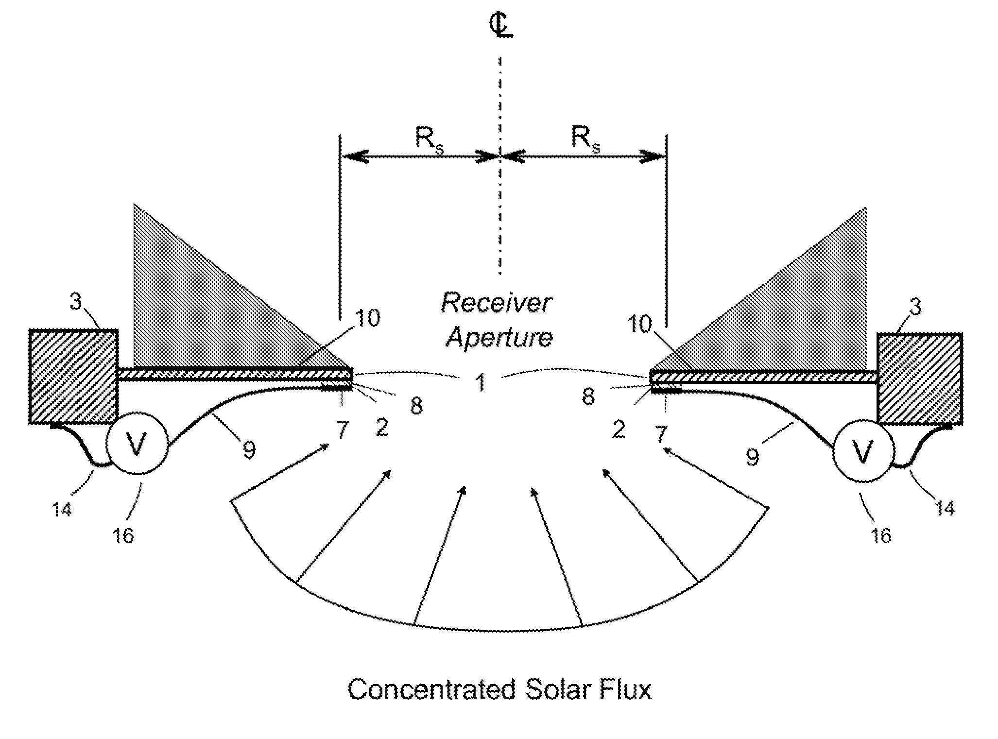
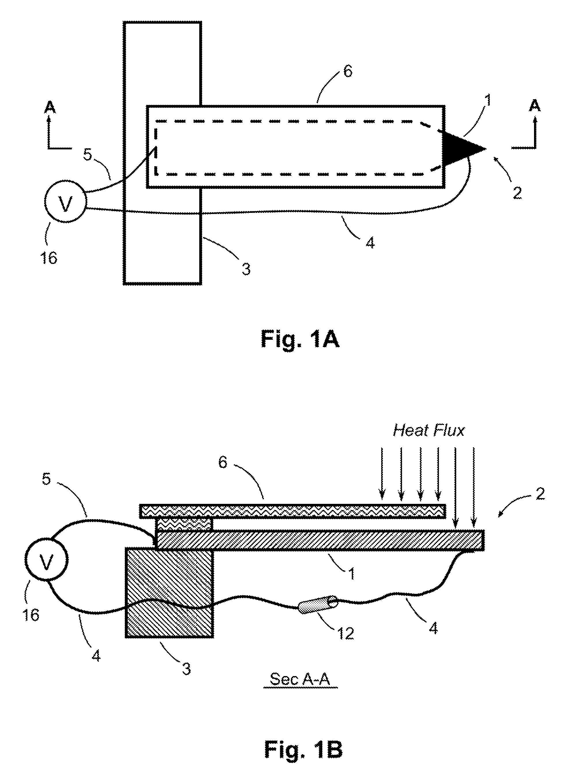
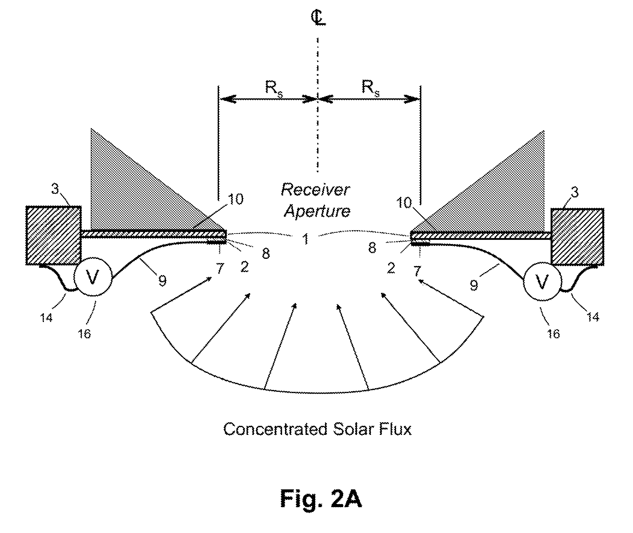
[0035]The tracking heat flux sensor of the present invention comprises two closely-coupled thermocouple junctions with opposing electrical polarity that are separated by a thermal resistor. This arrangement creates an electrical signal proportional to heat flux intensity, and largely independent of temperature. The sensors are thermally grounded to allow a temperature difference to develop across the thermal resistor; and are cooled by a heat sink to maintain an acceptable operating temperature.

[0036]In one embodiment, a tracking heat flux sensor can comprise: an absorber plate made of a first metal; a thermal bus made of the first metal; a thermal resistor plate made of a second metal different than the first metal, wherein the thermal resistor plate is attached to, and sandwiched in-between, the absorber plate and a near end of the thermal bus; a first dissimilar metal thermocouple junction located at an interface between the absorber plate and the resistor plate; a second dissimi...


PUM

PropertyMeasurementUnit
wedge angleaaaaaaaaaa
thickaaaaaaaaaa
thickaaaaaaaaaa

Abstract

Innovative tracking heat flux sensors located at or near the solar collector's focus for centering the concentrated image on a receiver assembly. With flux sensors mounted near a receiver's aperture, the flux gradient near the focus of a dish or trough collector can be used to precisely position the focused solar flux on the receiver. The heat flux sensors comprise two closely-coupled thermocouple junctions with opposing electrical polarity that are separated by a thermal resistor. This arrangement creates an electrical signal proportional to heat flux intensity, and largely independent of temperature. The sensors are thermally grounded to allow a temperature difference to develop across the thermal resistor, and are cooled by a heat sink to maintain an acceptable operating temperature.

Description

STATEMENT REGARDING FEDERALLY SPONSORED R&D[0001]The United States Government has rights in this invention pursuant to Department of Energy Contract No. DE-AC04-94AL85000 with Sandia Corporation.BACKGROUND OF THE INVENTION[0002]The present invention relates to tracking heat flux sensors used to accurately control the tracking of focused solar light for concentrating solar collectors, such as point-focus (dish) and line-focus (trough) collectors; as well as concentrating photovoltaic systems. The sensors can be passively cooled and mounted adjacent to the focus of the solar collectors.[0003]Concentrating Solar Power (CSP) systems convert the energy in concentrated sunlight into mechanical, electrical, or chemical energy. Accurate tracking of concentrating solar collectors is needed to enable higher concentration ratios and / or minimize the amount of reflected solar energy that misses the receiver. Open and closed-loop tracking are the two basic approaches for pointing the collector at...

Claims


Application Information

Patent Timeline
Patent Type & Authority Patents(United States)
IPC IPC(8): G01K17/00G01J5/14G01K7/02H01L35/00
CPCG01S3/7861G01K7/02G01K17/00F24J2/07Y02E10/41Y02E10/47F24J2002/385F24S20/20F24S2050/25Y02E10/40
Inventor ANDRAKA, CHARLES E.DIVER, JR., RICHARD B.
Owner NAT TECH & ENG SOLUTIONS OF SANDIA LLC
Why Eureka
Try Eureka