Ignition device for internal combustion engine
a technology for internal combustion engines and ignition devices, which is applied in the direction of machines/engines, installations with induction energy storage, other installations, etc., to achieve the effect of improving the function of a power circuit and accelerating the charging speed of a pj capacitor
- Summary
- Abstract
- Description
- Claims
- Application Information
AI Technical Summary
Benefits of technology
Problems solved by technology
Method used
Image
Examples
embodiment 1
Preferred Embodiment 1
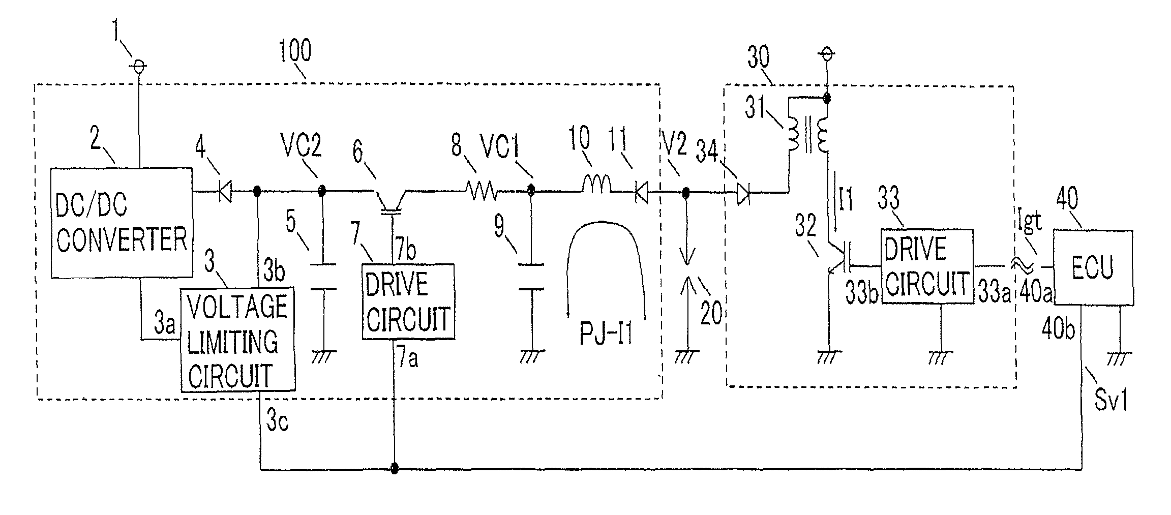
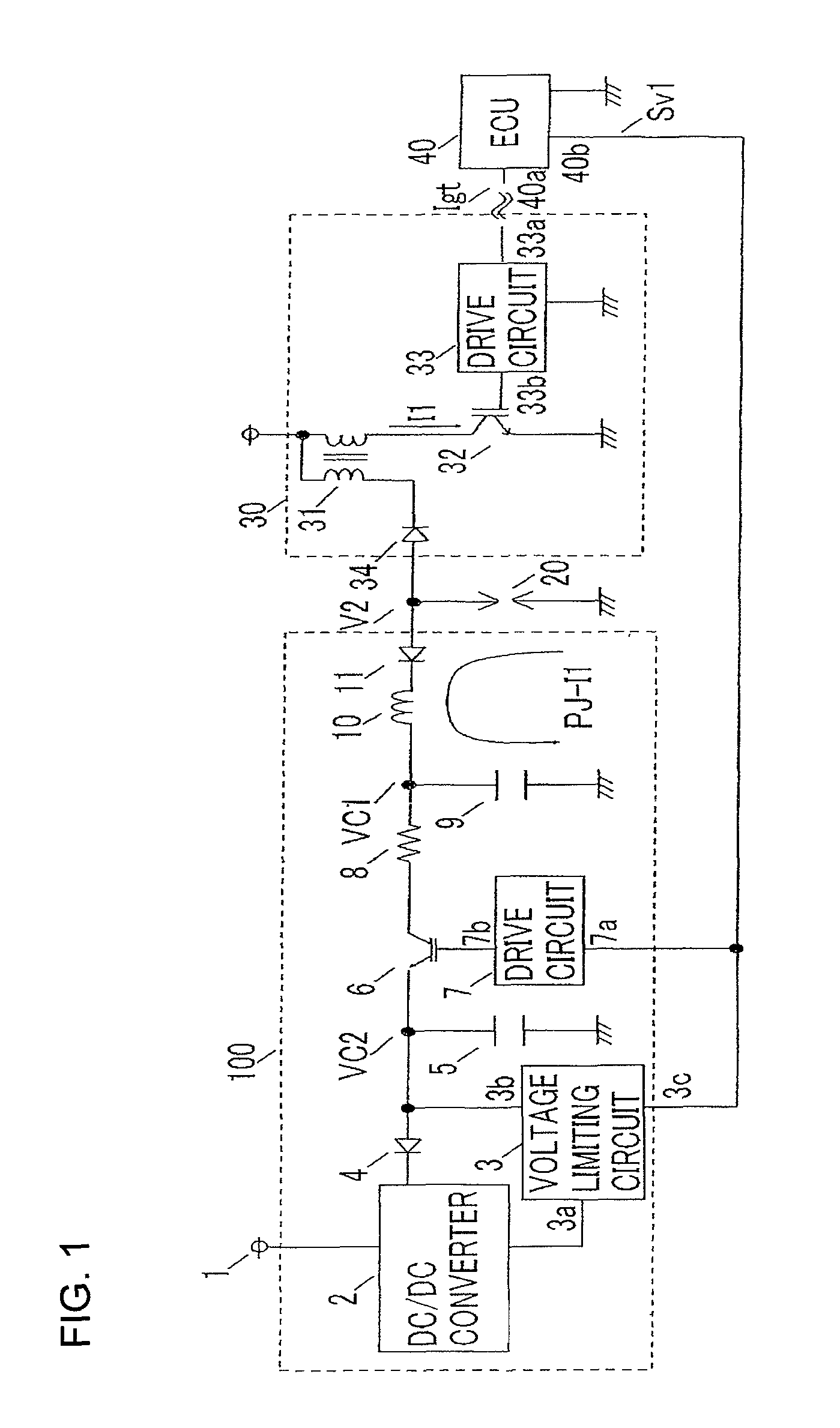
[0031]FIG. 1 is a circuit configuration diagram of an ignition device for an internal combustion engine of a preferred embodiment 1 of the present invention. In the drawing, the ignition device for the internal combustion engine of the preferred embodiment 1 is composed of a spark plug 20, an ignition circuit 30 which generates a high voltage on the basis of an ignition signal Igt from an electronic control unit (referred to as “ECU”) 40 in order to generate discharge in discharge space of the spark plug 20, and a power circuit 100 which generates a plasma current PJ-I1 in order to eject plasma by giving plasma energy to discharge space where impedance is lowered due to starting of discharge.
[0032]The ignition circuit 30 and the power circuit 100 are connected in parallel to each other with respect to the spark plug 20.
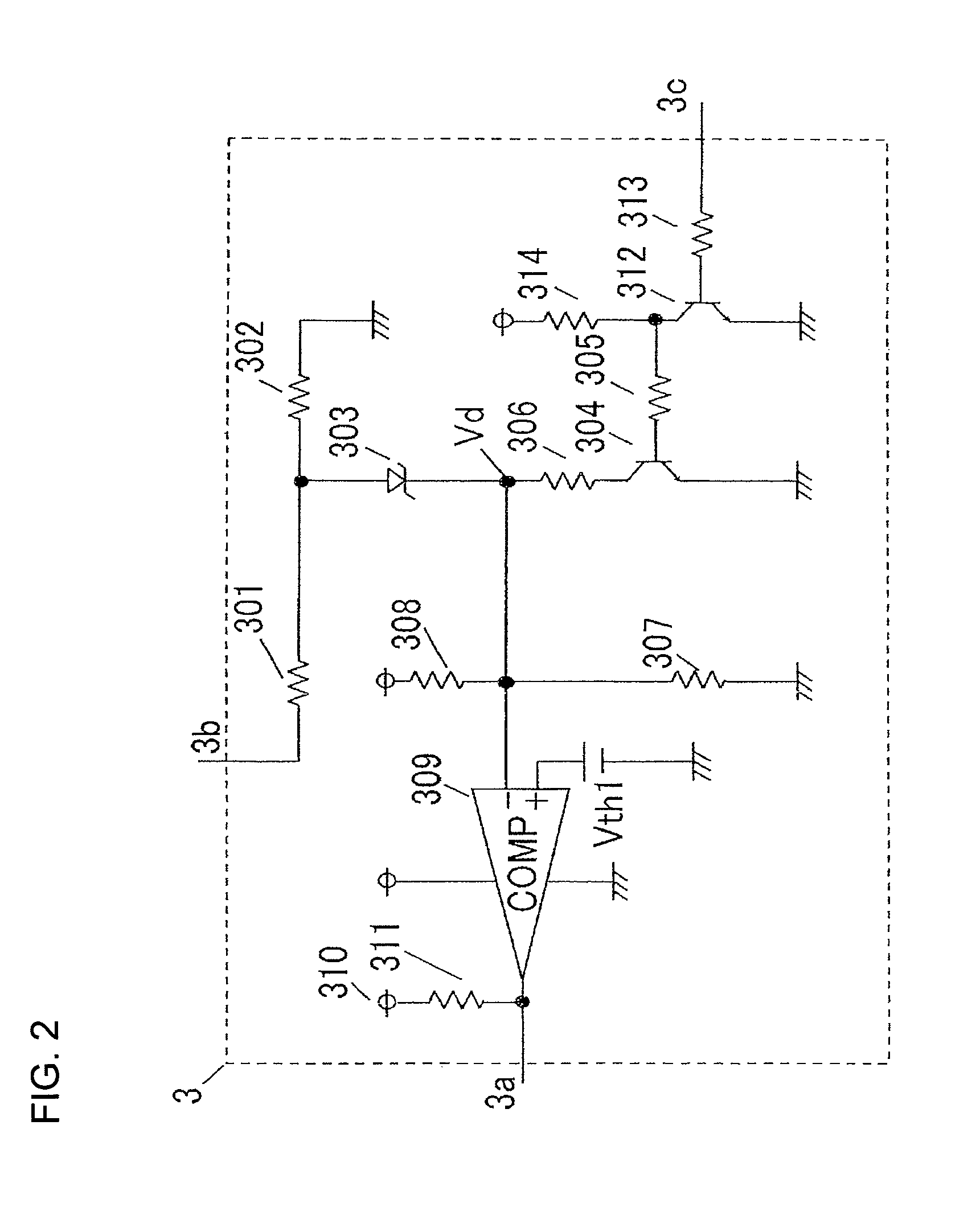
[0033]The power circuit 100 that is a major portion of the present invention includes a DC / DC converter 2, a voltage limiting circuit 3, a recti...
embodiment 2
Preferred Embodiment 2
[0057]In an ignition device for an internal combustion engine of a preferred embodiment 2 of the present invention, a voltage signal Sv1 outputted from an ECU 40 serves as an ignition signal Igt in the configuration of the preferred embodiment 1 in FIG. 1, and a timing chart at each operating point of the preferred embodiment 2 is shown in FIG. 4. Incidentally, the principle of operation is the same as that of the aforementioned preferred embodiment 1 and therefore description thereof will not be repeated.
[0058]Also in the preferred embodiment 2, as in the preferred embodiment 1, there is an effect that the charging speed of a PJ capacitor in the case when a high breakdown voltage switch is turned ON can be accelerated without changing a target charging voltage (target PJ energy) of the PJ capacitor 9.
embodiment 3
Preferred Embodiment 3
[0059]FIG. 5 is a circuit configuration diagram of an ignition device for an internal combustion engine of a preferred embodiment 3 of the present invention.
[0060]With respect to the plasma ignition device of the preferred embodiment 1 shown in FIG. 1, a plasma ignition device of the preferred embodiment 3 is further provided with an input terminal 3d on a voltage limiting circuit 3 and an output terminal 40c on an ECU 40 and a voltage signal Sv2 is further inputted from the output terminal 40c of the ECU 40 to the input terminal 3d of the voltage limiting circuit 3; and accordingly, a voltage limiting value of a tank capacitor 5 at the time when a high breakdown voltage switch 6 is OFF is set in multiple steps (plural numbers), and this configuration is denoted as a voltage limiting circuit 3′, a power circuit 100′, and an ECU 40′. Incidentally, other configuration is the same as that of the preferred embodiment 1 and therefore description thereof will not be ...
PUM
 Abstract
Description
Claims
Application Information
 - R&D
- Intellectual Property
- Life Sciences
- Materials
- Tech Scout
- Unparalleled Data Quality
- Higher Quality Content
- 60% Fewer Hallucinations
Browse by: Latest US Patents, China's latest patents, Technical Efficacy Thesaurus, Application Domain, Technology Topic, Popular Technical Reports.
© 2025 PatSnap. All rights reserved.Legal|Privacy policy|Modern Slavery Act Transparency Statement|Sitemap|About US| Contact US: help@patsnap.com


