Medical X-ray imaging system

a technology of x-ray imaging and x-ray radiation, applied in the direction of material analysis using wave/particle radiation, instruments, applications, etc., can solve the problems of low efficiency, large dimensions, heavy weight, etc., and achieve the effect of high quality

Active Publication Date: 2013-07-16
SIEMENS HEALTHCARE GMBH +1
View PDF12 Cites 7 Cited by
  • Summary
  • Abstract
  • Description
  • Claims
  • Application Information

AI Technical Summary

Benefits of technology

[0005]It is the object of the present invention to provide a medical X-ray imaging system which ensures the recorded X-ray images are of a high quality.
[0007]The medical X-ray imaging system according to the invention has a flat, planar X-ray source having a surface with X-ray focal points arranged adjacent to one another and an X-ray detector having a sensor surface, the X-ray source having a plurality of field emission guns with at least one field emission cathode and the surface with focal points of the X-ray source being larger in size than the sensor surface of the X-ray detector. The X-ray imaging system according to the invention has what is termed an inverse geometry, as a result of which the scattered radiation, for example, is significantly reduced, thereby lowering the exposure to radiation for patient and operator as well as increasing image quality. In contrast to known X-ray emitters, the field emission guns can be produced efficiently and economically in large numbers and with very small dimensions and used cost-effectively. Instead of a large X-ray detector, a relatively small, though at the same time very powerful and efficient X-ray detector is used, as a result of which the image quality of the recorded X-ray images can likewise be improved. What is to be understood by the surface with the focal points of the X-ray source is the two-dimensional area over which the field emission guns are distributed, the field emission guns or, more accurately, their focal points being arranged as densely as possible.
[0009]Overall, by virtue of the field emission guns the invention has the advantages of low heat generation by the X-ray source and a low weight, attributable not only to the field emission guns themselves but also to the omission or reduction in size of a cooling system. Compared with conventional X-ray emitters, field emission guns are also extremely compact, which is a prerequisite for making a high-quality, planar X-ray source having a surface of many focal points arranged adjacent to one another possible in the first place. This is ensured in particular by an array having a plurality of field emission guns. The lifespan of field emission guns is also significantly longer than that of known X-ray emitters with thermal cathodes. Compared with a thermal cathode, a field emission cathode can also be started quickly without heating. By virtue of the easily focusable electron current a higher spatial resolution can additionally be achieved for X-ray images. All in all, an X-ray source having field emission guns is also particularly suitable for new applications in which rapid movements of the X-ray source or of the entire imaging systems consisting of X-ray source and X-ray detector are necessary.

Problems solved by technology

Known vacuum tubes have among other things the disadvantages of heavy weight (both due to their intrinsic weight and due to an additionally necessary water cooling system), large dimensions, a low level of efficiency, and in particular significant heat generation.
Limiting factors affecting image quality in this case are, inter alia, scattered radiation and the limited efficiency of the detector.

Method used


Image

  • Medical X-ray imaging system
  • Medical X-ray imaging system
  • Medical X-ray imaging system

Examples


Embodiment Construction

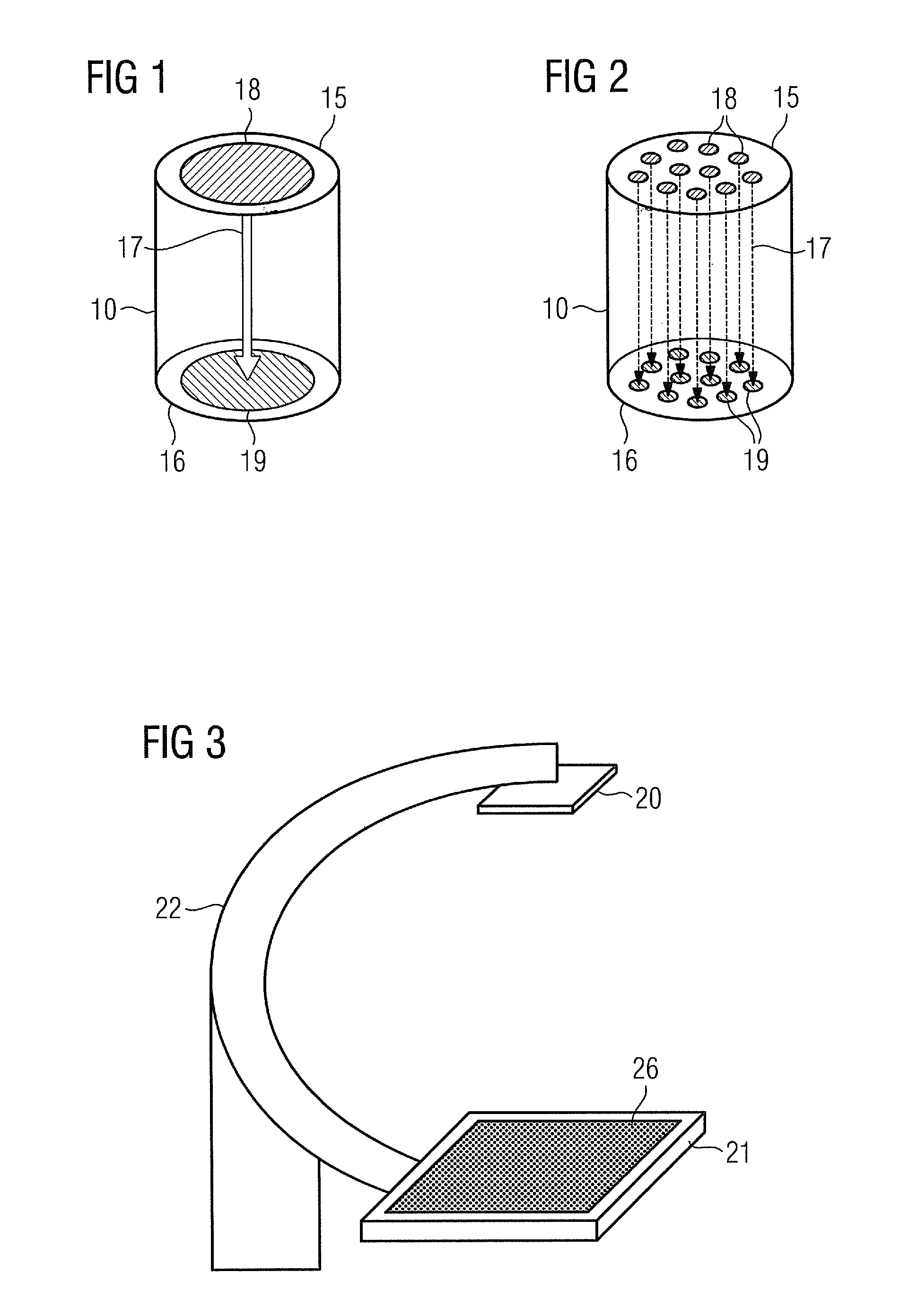
[0020]FIG. 1 shows a field emission gun 10 with a cathode 15 having a (single) electron-emitting element 18 and an anode 16 having a (single) focal point 19. In this case the material that is particularly well suited as a cathode for generating the high electron current densities necessary is carbon, in particular in the form of nanotubes (CNT cathode). By application of a corresponding electric field the electron-emitting element 18 is stimulated without heating to emit an electron beam 17 which subsequently strikes the anode 16 or, as the case may be, focal point 19 and generates X-radiation there.

[0021]FIG. 2 shows a further embodiment of a field emission gun 10 which has a cathode having a plurality of electron-emitting elements 18, all of which can be activated individually. In this case the elements 18 can be arranged in the manner of pixels. The anode 16 too consists of a plurality of focal points 19, each electron-emitting element 18 being assigned a focal point 19. The anod...


PUM

PropertyMeasurementUnit
weightaaaaaaaaaa
timeaaaaaaaaaa
sizeaaaaaaaaaa

Abstract

In order to achieve improved image quality in X-ray photographs, a medical X-ray imaging system, comprising a flat, planar X-ray source having a surface with X-ray focal points arranged adjacent to one another and an X-ray detector with a sensor surface, is provided. The X-ray source has a plurality of field emission guns with at least one field emission cathode and the surface with focal points of the X-ray source is larger in size than the sensor surface of the X-ray detector.

Description

CROSS REFERENCE TO RELATED APPLICATIONS[0001]This application claims priority of German application No. 10 2009 058 266.5 filed Dec. 14, 2009, which is incorporated by reference herein in its entirety.FIELD OF THE INVENTION[0002]The invention relates to a medical X-ray imaging system.BACKGROUND OF THE INVENTION[0003]Vacuum tubes have been used for decades in the well-known medical X-ray technology field as X-ray sources for generating ionizing X-radiation. In these applications an electron beam is emitted from a metal filament cathode heated to over 1000° C. in an evacuated glass tube and accelerated toward a metal anode made, for example, of tungsten, as a result of which X-radiation is generated. A vacuum tube of said kind having a rotating anode is known from U.S. Pat. No. 4,326,144, for example. Known vacuum tubes have among other things the disadvantages of heavy weight (both due to their intrinsic weight and due to an additionally necessary water cooling system), large dimensi...

Claims


Application Information

Patent Timeline
Patent Type & Authority Patents(United States)
IPC IPC(8): G01N23/04H01J35/02
CPCA61B6/4233A61B6/4021A61B6/4441H01J2235/062
Inventor BOESE, JANFURST, JENSMASCHKE, MICHAELSPRENGER, FRANK
Owner SIEMENS HEALTHCARE GMBH
Why Eureka
Try Eureka