System and method for stacking receiver channels for increased system through-put in an RF data transmission system

a technology of data transmission system and receiver channel, which is applied in the direction of transmission monitoring, frequency-division multiplex, instruments, etc., can solve the problems of complex design and excessive interference of robust control channels, and achieve the effect of more flexibility in the design of a network and more flexibility in mitigating interferen

Active Publication Date: 2013-07-23
NETGEAR INC
View PDF34 Cites 25 Cited by
  • Summary
  • Abstract
  • Description
  • Claims
  • Application Information

AI Technical Summary

Benefits of technology

[0012]Advantageously, using narrower bandwidth channels rather than higher bandwidth channels to communicate with users, gives a frequency planner more flexibility in the design of a network, and gives the system more flexibility in mitigating any interference that might arise. For example, if interference occurs on one of the two channels that is being transmitted to the user, there are more narrow band channels available for the hub to select from for future transmissions. The present system is well adapted for use in a frequency duplex system, a time duplex system, a time division duplexing (TDD) system or other similar duplexing or multiplexing systems.

Problems solved by technology

In the prior art changing the modulation scheme of a data channel required a bursty receiver, which is a more complicated design than a continuous receiver.
The robust control channel may also experience excessive interference.
Also, if there is a failure in the system resulting in loss of one channel or if interference on one of the channels becomes unacceptably high, the system can continue to communicate via the remaining channel, albeit at a lower data transfer rate.

Method used


Image

  • System and method for stacking receiver channels for increased system through-put in an RF data transmission system
  • System and method for stacking receiver channels for increased system through-put in an RF data transmission system
  • System and method for stacking receiver channels for increased system through-put in an RF data transmission system

Examples


Embodiment Construction

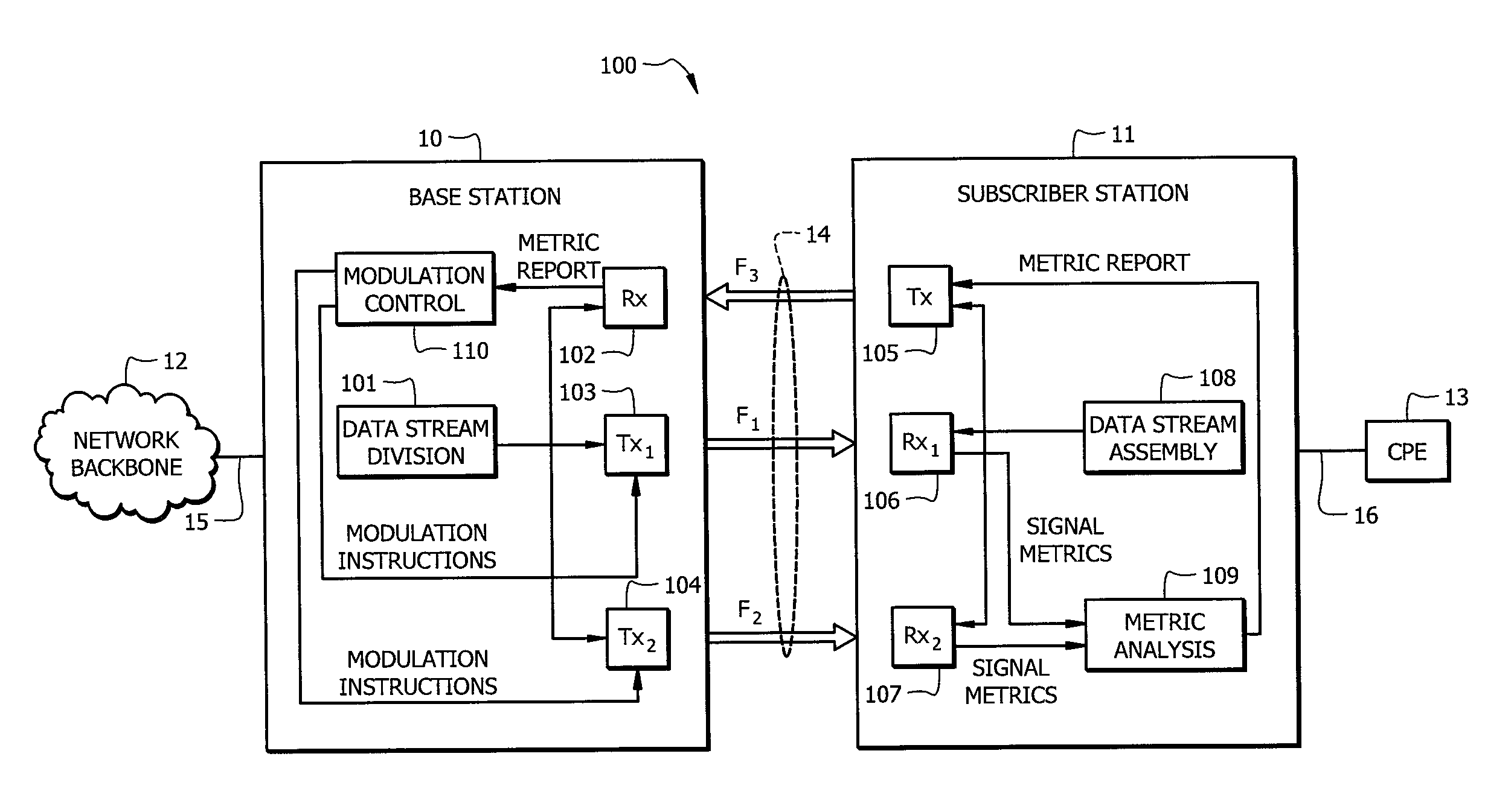
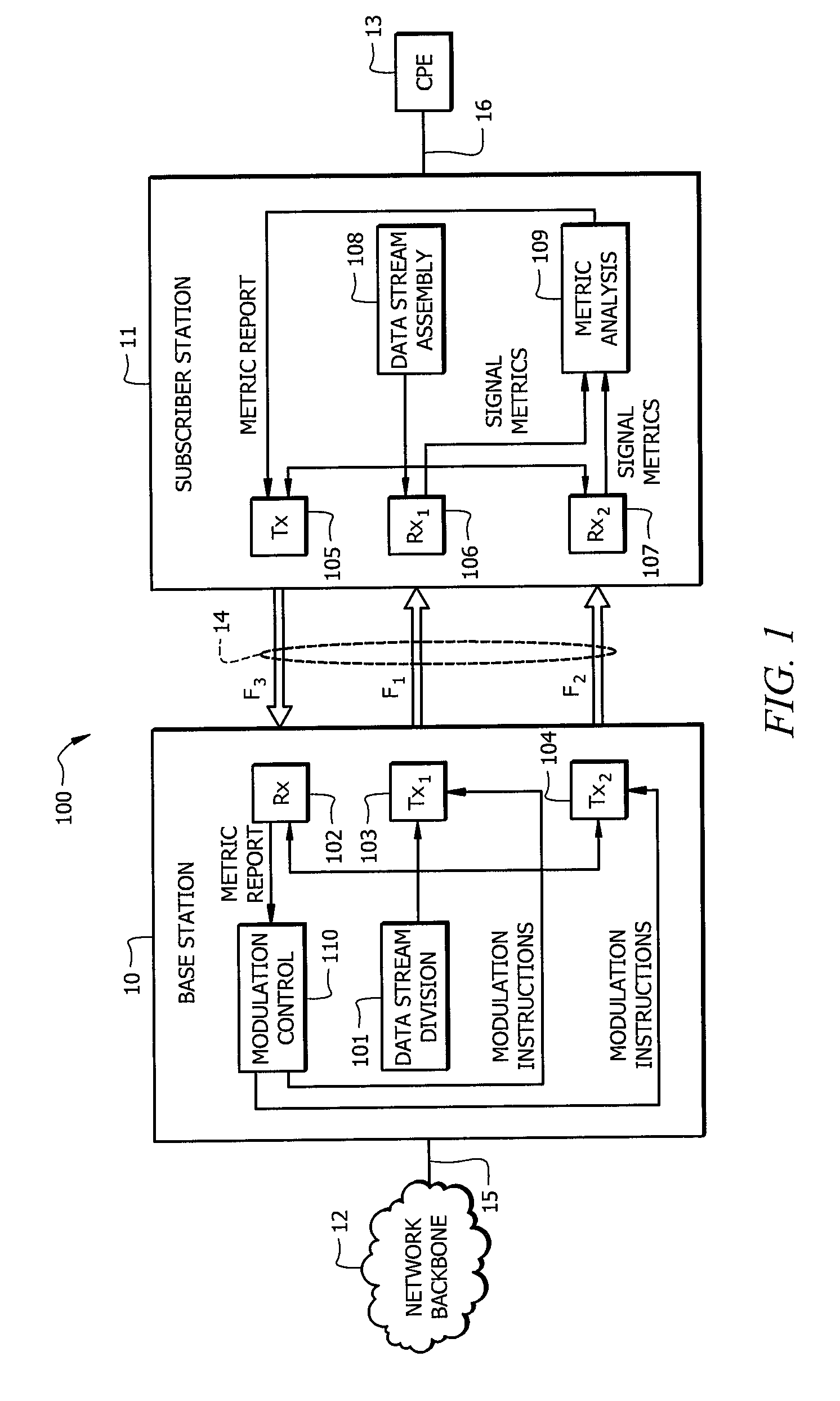
[0017]FIG. 1 shows system 100, which provides a data communication connection between hub base station 10 and subscriber station 11. In this system, the connection between base 10 and subscriber 11 is through RF transmission medium 14, preferably employing channels F1, F2 and F3. The illustrated base station has two transmitters, 103 and 104, and the subscriber station has two or more receivers 106 and 107. The hub 10 can provide an enhanced data transmission rate from the hub 10 to the subscriber 11 employing both hub transmitters 103 and 104 for reception by subscriber receivers 106 and 107. Transmitters 103, 104 and 105 and receivers 102, 106 and 107 are designed to transmit and receive using a digital transmission scheme, preferably one whose data rate can be modified based on channel conditions. For example, BPSK or a higher rate modulation scheme, including but not limited to QPSK, 16QAM, 64QAM or 256QAM may be used. Other modulation schemes, such as multilevel PSK, may be use...


PUM


Abstract

A wireless RF data transmission system has at least one base station transmitting control information on a control channel and high speed data on at least one data channel. At least one subscriber station receives the control information and data channels, adjusting a modulation and/or coding of reception of the data in response to the control information. Preferably, the control information is transmitted using a more robust modulation, such as QPSK, than used to transmit the data, which is preferably transmitted using either 16, 64 or 256 QAM. Additionally, timing or header information for the data may be included on the control channel.

Description

TECHNICAL FIELD[0001]The present invention relates to RF data transmission systems and specifically to a system and method for stacking receiver channels for increased system through-put in an RF data transmission system.BACKGROUND[0002]Currently, there are several so-called “last mile” and “last foot” data transmission systems which are designed to deliver high speed and / or high data capacity from the internet backbone to an end user. Several such systems use RF transmissions to replace copper wire or fiber optic cables. Some of these systems are called point-to-point or point-to-multipoint systems and operate in various licensed and unlicensed RF bands. A fundamental characteristic of many such existing systems is that their RF transmissions occur in a frequency spectrum protected and regulated by a government body. These protected frequency spectrums, or bands, are licensed to certain license holders and only a few may operate in any given physical area depending upon the number ...

Claims


Application Information

Patent Timeline
Patent Type & Authority Patents(United States)
IPC IPC(8): H04L27/00
CPCH04L1/0025H04L1/0039H04L5/06H04L27/34H04L5/1469H04L1/0003H04W72/20H04B17/30H04B15/00
Inventor REUDINK, MARK D.DUNBAR, LEEROTHAAR, BRUCE C.
Owner NETGEAR INC
Why Eureka
Try Eureka