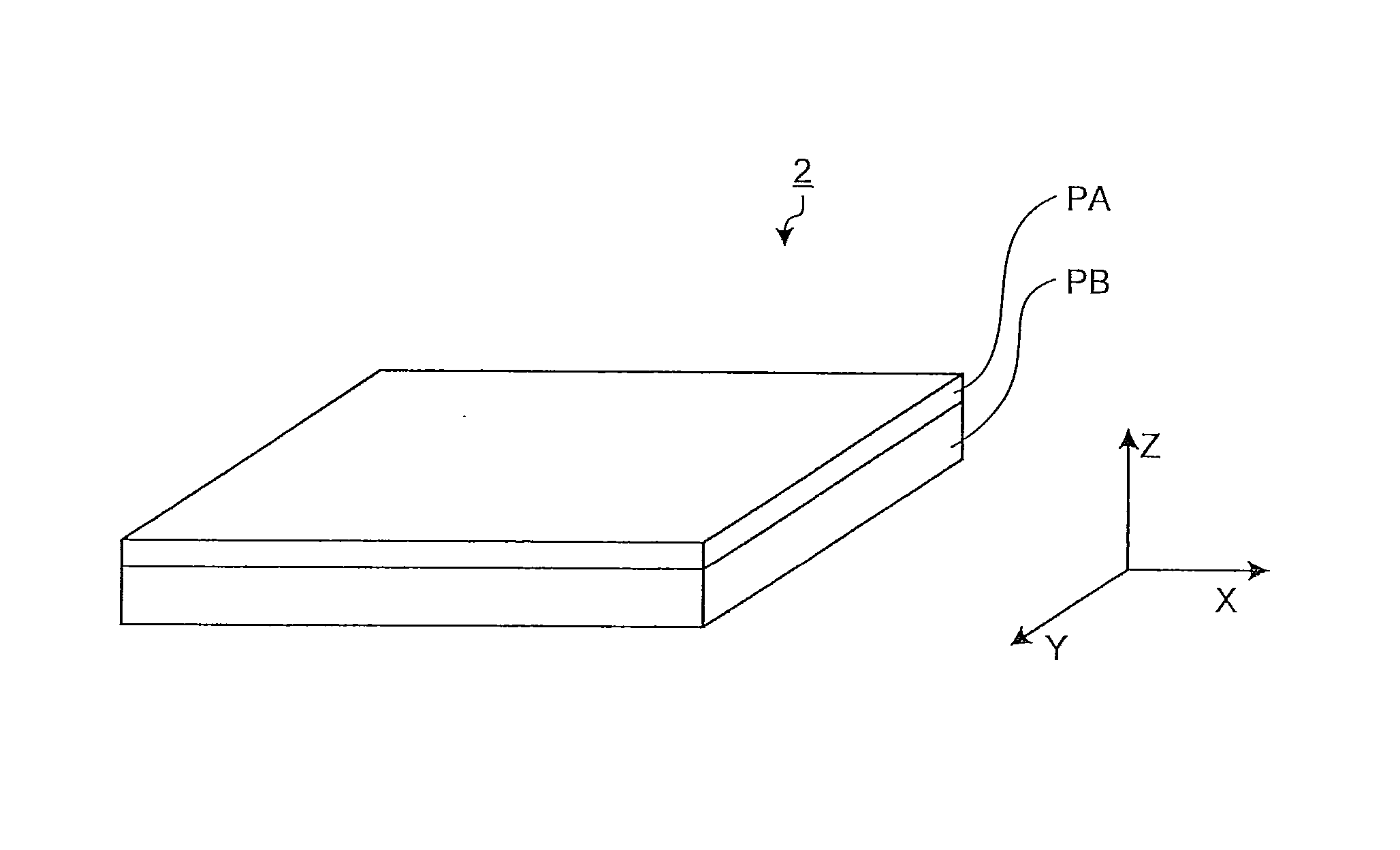
Optical film and liquid crystal display
a liquid crystal display and optical film technology, applied in the direction of synthetic resin layered products, instruments, manufacturing tools, etc., can solve the problems of inability to reduce the color tone change due to observation angle shift, inappropriate hardness and flexibility of stretched films, and resins with negative intrinsic birefringence values such as polystyrene, etc., to achieve easy manufacturing, low cost, and large area
- Summary
- Abstract
- Description
- Claims
- Application Information
AI Technical Summary
Benefits of technology
Problems solved by technology
Method used
Image
Examples
example 1
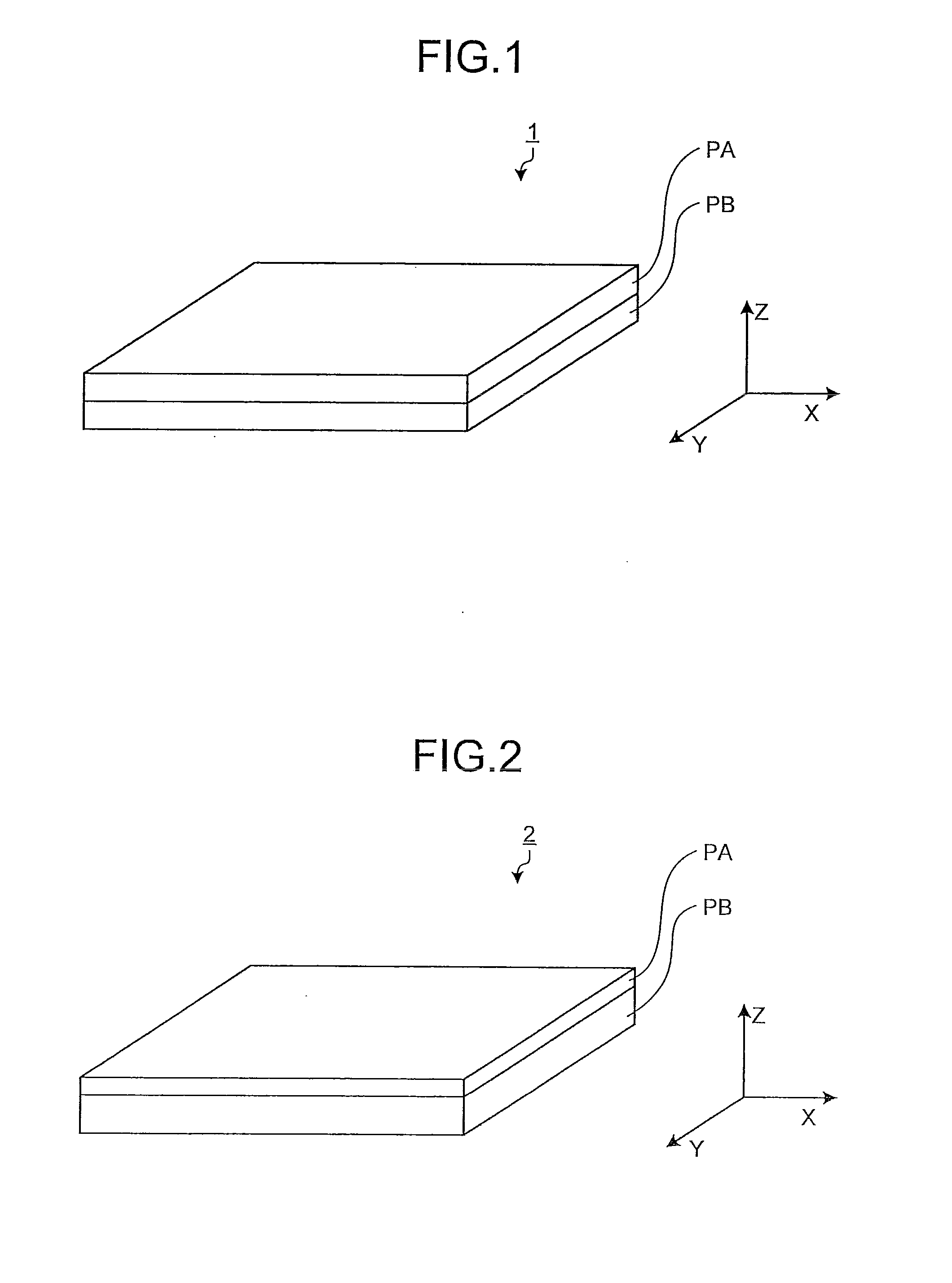
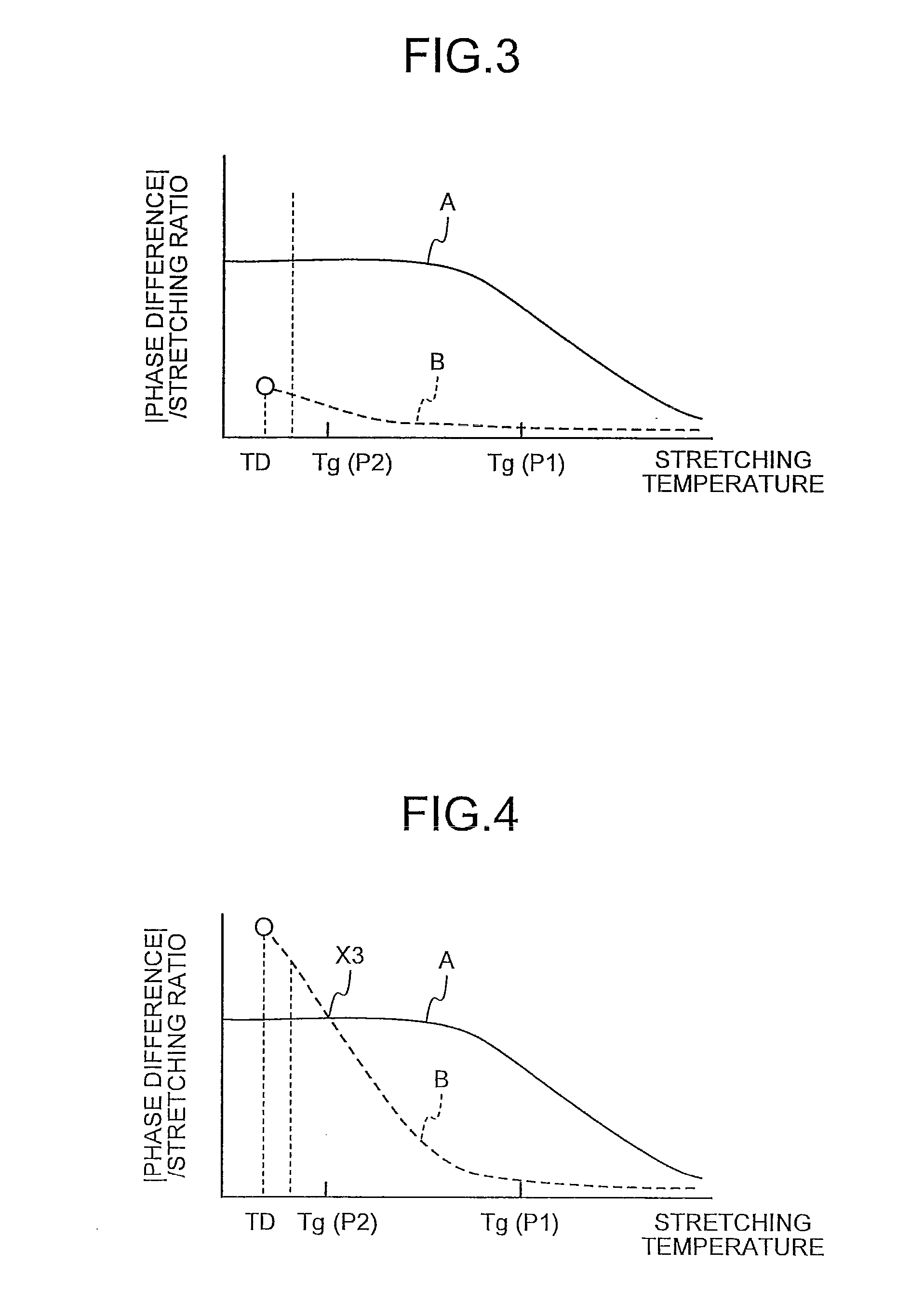
[0100]75 parts by weight of the hydrogenated polynorbornene obtained in Preparative Example 1 and 25 parts by weight of polystyrene (product name “HF77,” product of PS Japan Corporation) were dissolved in chloroform to produce a dope solution P1. The concentration of the solids in the dope solution P1 (the ratio of the total amount of the resins relative to the total amount of the solution) was adjusted to 20 percent by weight.
[0101]75 Parts by weight of polystyrene (product name “HF77,” product of PS Japan Corporation) and 25 parts by weight of poly(2,6-dimethyl-1,4-phenylene oxide) (catalog No 18242-7, ALDRICH) were dissolved in chloroform to produce a dope solution P2. The concentration of the solids in the dope solution P2 was adjusted to 20 percent by weight.
[0102]The dope solution P1 was flow-casted on a glass plate using a doctor blade and dried to form a transparent resin layer A1 having a thickness of 200 μm. Then the dope solution P2 was flow-casted on the transparent resi...
example 2
[0107]The dope solution P1 was flow-casted on a glass plate using a doctor blade and dried to form a transparent resin layer A4 having a thickness of 230 μm. Then the dope solution P2 was flow-casted on the transparent resin layer A4 using a doctor blade and dried to form a transparent resin layer B4 having a thickness of 270 μm. The transparent resin layer A4 together with the transparent resin layer B4 was peeled off the glass plate to produce a stacked film 4 having the transparent resin layers A4 and B4.
[0108]One in-plane direction in the stacked film 4 was defined as the X axis. The stacked film 4 was stretched by a factor of 3.2 in this direction at 130° C. and then stretched by a factor of 1.25 in the Y axis direction that was orthogonal to the X axis direction at 105° C. to obtain a phase difference film 4 having a thickness of 130 μm.
[0109]R450, R550, R650, and R40 of the phase difference film 4 were measured. The results are shown in Table 1. As is clear from the results i...
example 3
[0111]78 Parts by weight of the hydrogenated polynorbornene obtained in Preparative Example 1 and 22 parts by weight of polystyrene (product name “HF77,” product of PS Japan Corporation) were dissolved in chloroform to produce a dope solution P5. The concentration of the solids in the dope solution P5 (the ratio of the total amount of the resins to the total amount of the solution) was adjusted to 20 percent by weight.
[0112]78 Parts by weight of polystyrene (product name “HF77,” product of PS Japan Corporation) and 22 parts by weight of poly(2,6-dimethyl-1,4-phenylene oxide) (catalog No 18242-7, ALDRICH) were dissolved in chloroform to produce a dope solution P6. The concentration of the solids in the dope solution P6 was adjusted to 20 percent by weight.
[0113]The dope solution P5 was flow-casted on a glass plate using a doctor blade and dried to form a transparent resin layer A5 having a thickness of 200 μm. Then the dope solution P6 was flow-casted on the transparent resin layer A...
PUM
| Property | Measurement | Unit |
|---|---|---|
| incident angle | aaaaa | aaaaa |
| wavelength | aaaaa | aaaaa |
| wavelength | aaaaa | aaaaa |
Abstract
Description
Claims
Application Information
 - R&D
- Intellectual Property
- Life Sciences
- Materials
- Tech Scout
- Unparalleled Data Quality
- Higher Quality Content
- 60% Fewer Hallucinations
Browse by: Latest US Patents, China's latest patents, Technical Efficacy Thesaurus, Application Domain, Technology Topic, Popular Technical Reports.
© 2025 PatSnap. All rights reserved.Legal|Privacy policy|Modern Slavery Act Transparency Statement|Sitemap|About US| Contact US: help@patsnap.com


