H-bridge pulse generator

a pulse generator and hbridge technology, applied in mechanical vibration separation, electrical equipment, transmission, etc., can solve the problems of parasitic components and undesirable ringing, and achieve the effects of reducing the propagation delay to output, increasing efficiency and electrical power, and improving stability

Inactive Publication Date: 2013-08-13
SMITH STEPHEN
View PDF7 Cites 3 Cited by
  • Summary
  • Abstract
  • Description
  • Claims
  • Application Information

AI Technical Summary

Benefits of technology

[0012]The invention is an electronic circuit that produces greater power output power, increased efficiency, a wider frequency response and reduces ring-down noise in a physically smaller package compared to conventional RF pulsers for EMATs. Specifically, the H-bridge circuit topology provides several advantages for the EMAT pulser. This circuit can produce transmitters pulses that are normally impeded by the transformer that is required with the push pull design. Additionally the output impedance of the design will be low with the upper two switches closed or the lower two switches closed.
[0013]This invention consists of arrangements of electronic circuits that are based on H-Bridge topology for the purpose of producing greater output power, increased efficiency, a wider frequency response and reducing ring-down noise in a physically smaller package compared to RF pulse sources typically used with EMATs. The basic H-bridge circuit has been modified and augmented primarily by connecting the switching devices, e.g., power MOSFETs, in parallel is some or all of the branches of the H-bridge configuration. Driver circuits have been designed and pulsing sequences have been devised to improve stability, distribute the current supplied to the load evenly among the switching devices and to generate output waveforms that improve the performance of the EMAT.
[0015]An additional benefit of the current invention is the propagation delay to output is reduced by removal of transformer. The currents flowing through the transformer with the parasitic components creates an undesirable phase delay that is reduced without transformer. The parasitic components also create an undesirable ringing when the switches turn off the transformer, which appears to the output that is removed with present design. The High Frequency Mosfets used in the H Bridge are rated for the load current and voltage rating of at least 88VDC to prevent failures. This is a benefit of using an H-bridge instead of the original design, for the voltage across the devices would have to be twice the voltage for a given buss voltage, which limits the choices of electronic component that can be used.
[0016]A circuit has been designed in which a diode is connected in series with each of the switching devices in the branches of the H-bridge to protect the device from damaging reverse currents. An optically coupled driver circuit has been designed to improve stability. A circuit has been designed whereby a plurality of switching devices is connected in parallel in the lower branches of the H-bridge configuration so that when the switching devices are turned on and off in the proper timed squences the unwanted transient electrical output currents flowing through an inductive load such as an EMAT coil are quenched. A circuit has been designed in which a plurality of switching devices such as power Mosfets connected in parallel in all branches of the H-bridge configuration whereby the switching device are turned on and off in timed sequences that results in increased efficiency and greater electrical power delivered to the inductive load. A circuit has been designed in which a plurality of switching devices are connected in parallel in all branches of the H-bridge configuration whereby the switching devices in the same branch to be turned on and off in timed sequences that allow the other switching devices in the same branch to be turned off when any one of the switching devices in that branch is turned on thereby increasing the efficiency of the pulser in delivering increased electrical power to the inductive load. A logic circuit has been designed that is comprised of four units, each containing an RS Flip-Flop, a delay and 2 AND gates that provide the drive inputs to each of the Mosfets in proper sequence for the generation of current outputs from each of the switching devices in a branch of the H-bridge and delivers current to the inductive load while the other switching devices in a branch are turned off. A circuit has been designed where a plurality of H-bridges each containing switching devices such as Mosfets with outputs coupled in parallel through transformer windings in all branches the H-bridge configuration whereby the switching devices are turned on and off in timed sequences resulting in amplitude modulated output voltage and current that is concentrated in select narrow power spectra.

Problems solved by technology

The currents flowing through the transformer with the parasitic components creates an undesirable phase delay that is reduced without transformer.
The parasitic components also create an undesirable ringing when the switches turn off the transformer, which appears to the output that is removed with present design.

Method used


Image

  • H-bridge pulse generator
  • H-bridge pulse generator
  • H-bridge pulse generator

Examples


Embodiment Construction

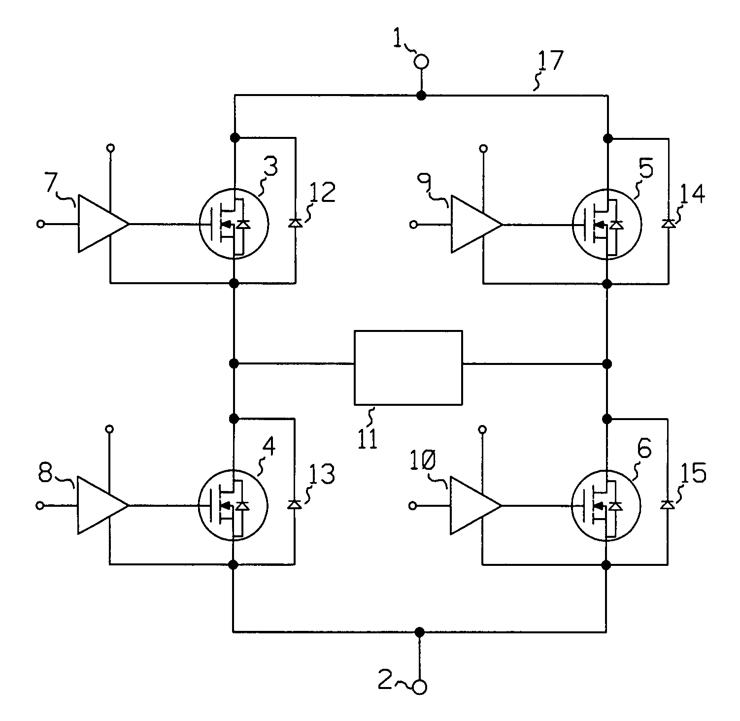
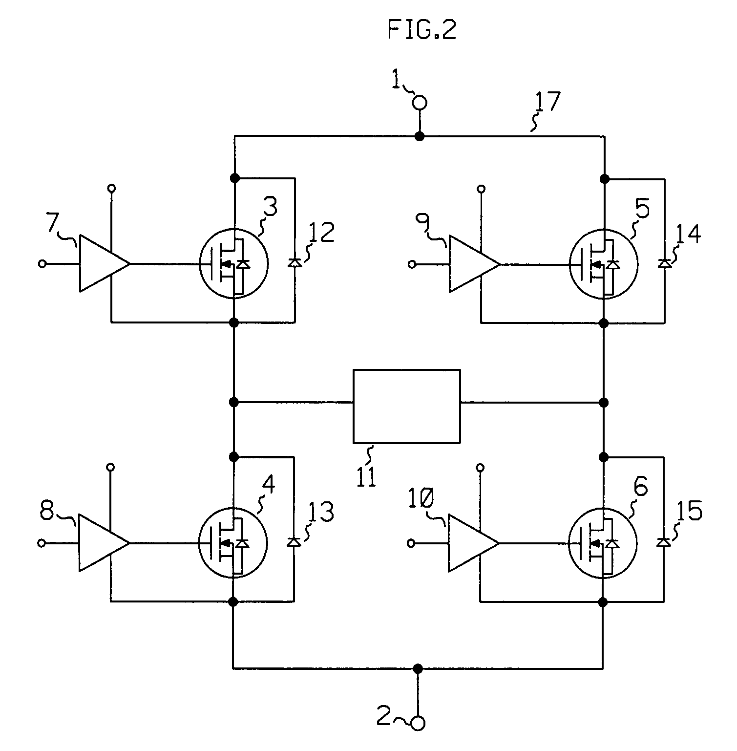
[0029]FIG. 2 is a schematic diagram of the primary embodiment of this invention. The H-bridge circuit 17 eliminates the transformer and provides a means for high-speed switching circuit, bipolar-high voltage, variable frequency excitation and elimination of unwanted oscillations frequency, reversible output, quenching of output, with various modes of operation for use of transmission of various outputs for EMAT transducers.

[0030]The load, 11, may or may not include a transformer. If the transformer is eliminated the H-bridge circuit, 17, provides a means for high speed switching of a bipolar, high voltage, at a variable frequency excitation. This facilitates the elimination of wanted oscillations frequency, the provision for reversible output polarity, and quenching of transient output noise by the incorporation of various circuit modifications and modes of operation. Additional circuit and operational modifications are applied to increase output power, frequency bandwidth and vario...


PUM


Abstract

Circuitry for high-power, high-frequency excitation of electromagnetic acoustic transducers (EMAT) without the use of a matching transformer is described. This circuit contains at least 4 switching devices, arranged in an H-Bridge configuration to drive EMATs over a range of frequencies. The switching devices can be connected in parallel with respect to the H-Bridge and switched in sequence for greater power output and variety of wave forms including, Churp, Hemming window tone burst, rectangular tone burst and Barker Code wave forms. A circuit for driving sensor coils of an EMAT to correct the disadvantages of conventional pulsers. A plurality of switching devices are connected in parallel and augmented with support circuitry to provide increased power output, stability, reduced noise and complex output wave forms. This design provides for the application of modulated pulses such as multi-pulse, multi-frequency bursts with peak power outputs over 20,000 watts and frequencies over 10,000 Hertz.

Description

[0001]This application is a Continuation-In-Part of application Ser. No. 11 / 786,538 fo;ed Apr. 12, 2007, entitled H-BRIDGE PULSE GENERATOR, now abandonedBACKGROUND OF THE FIELD[0002]EMAT driver circuit has typically used a push-pull topology as illustrated in FIG. 1. This circuit provides a tone burst of current consisting of a specified number of cycles in the EMAT transmitter coil.[0003]In the past EMATS (electromagnetic acoustic transducers) have typically used a push-pull topology. This type of circuit provides a tone burst of current consisting of a specified number of cycles in the EMAT transmitter coil. The system would be switched on for a period of time and then switched off for a period of time, followed by the switching on for the same period of time another coil to avoid saturation of the transformer and then switching it off at the end of the cycle. This cycle produces a square wave output that can be transformed into the voltage required to drive the EMAT and its tunin...

Claims


Application Information

Patent Timeline
Patent Type & Authority Patents(United States)
IPC IPC(8): H04B1/02
CPCB06B1/0215B06B1/0269
Inventor SMITH, STEPHEN
Owner SMITH STEPHEN
Why Eureka
Try Eureka