Engine with emissions control arrangement and method of controlling engine emissions

a technology of engine emissions and emission control, applied in the direction of electric control, machines/engines, mechanical equipment, etc., can solve the problems of poor aerodynamic characteristics, limited vehicle design, and tendency to drive up heat rejection, so as to reduce heat rejection, improve fuel consumption, and reduce the effect of egr us

Active Publication Date: 2013-08-20
VOLVO LASTVAGNAR AB
View PDF25 Cites 6 Cited by
  • Summary
  • Abstract
  • Description
  • Claims
  • Application Information

AI Technical Summary

Benefits of technology

[0002]Exhaust gas recirculation (EGR) systems, which introduce a portion of the exhaust gases into the engine intake, dilute the oxygen in the incoming air charge and can lower combustion temperatures. Accordingly, EGR systems can be useful in reducing engine NOx emissions. The amount of EGR flow can be controlled by an EGR controller such as an EGR valve, a turbocharger, such as a variable geometry turbocharger (VGT), an exhaust backpressure device, an intake throttle, and the like, and, typically, by some combination of two or more of these controllers.
[0007]It is desirable to maintain NOx emissions at or below predetermined levels, such as those set in the various regulations. It is also desirable to minimize EGR use and thereby reduce heat rejection, improve fuel consumption, and increase power density.

Problems solved by technology

One problem with EGR systems is that they tend to drive up heat rejection.
This, in turn, typically imposes limitations on vehicle designs, such as necessitating large front faces having poor aerodynamic characteristics.
Another problem with EGR systems is that they tend to increase fuel consumption.
In addition to fuel consumption increases due to limits on vehicle aerodynamics and cooling fan power consumption, it is necessary to create sufficient exhaust back pressure to force the exhaust gas through the cooler and into the intake system.
These “pumping” losses can be substantial.
Yet another problem with EGR systems is that they tend to lower power density, i.e., power output is lower relative to displacement.

Method used


Image

  • Engine with emissions control arrangement and method of controlling engine emissions
  • Engine with emissions control arrangement and method of controlling engine emissions

Examples


Embodiment Construction

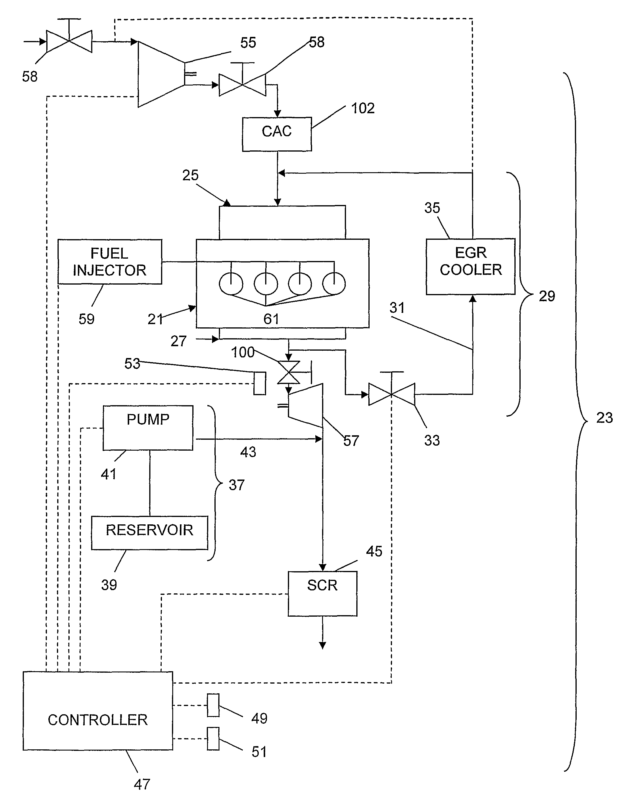
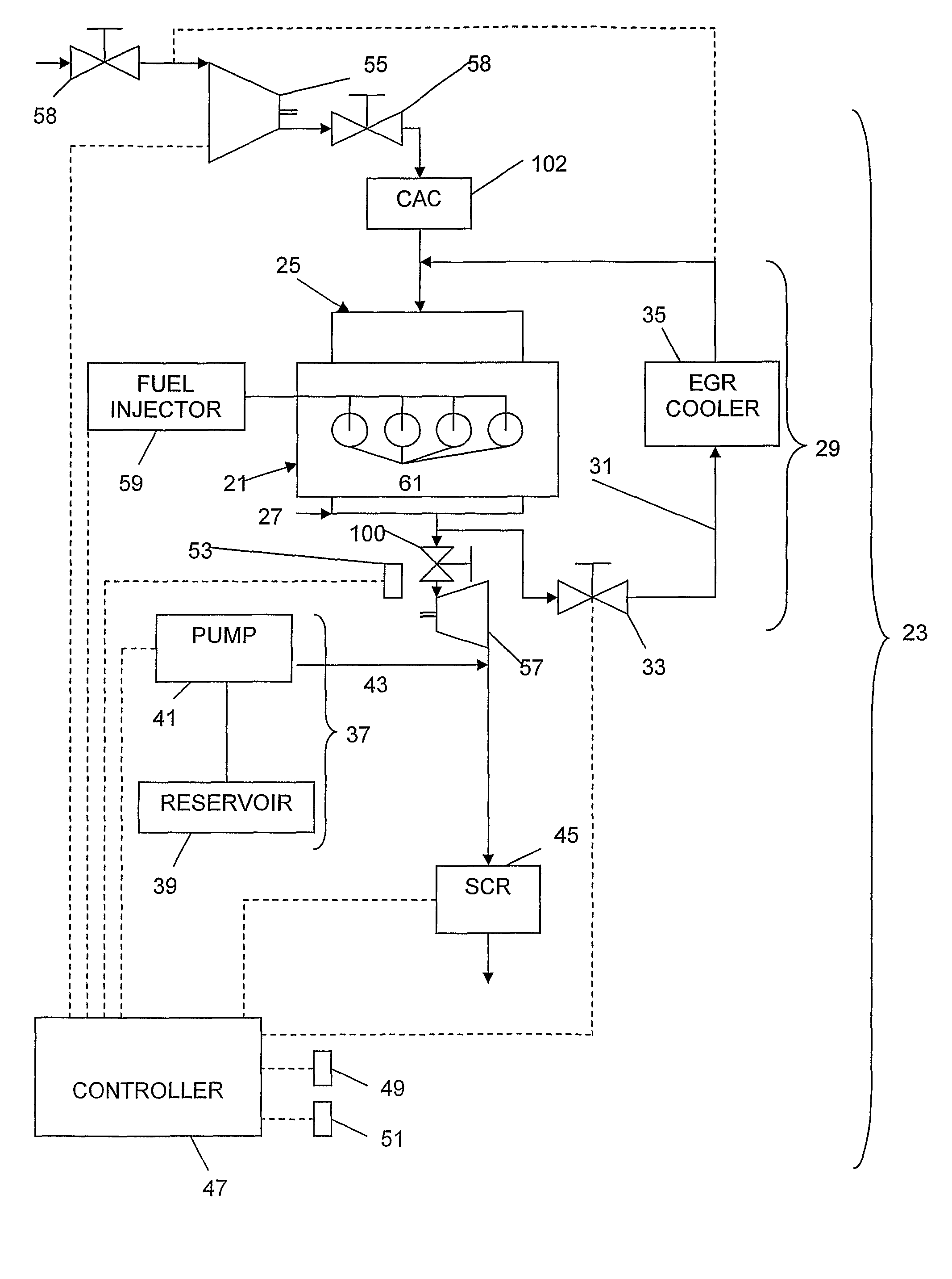
[0012]An engine 21 with an emissions control arrangement 23 according to an aspect of the present invention is shown in FIG. 1. The engine 21 includes an intake 25, such as an intake manifold, and an exhaust system 27.

[0013]An EGR system 29 is also provided and comprises a conduit 31 between the exhaust system 27 and the intake 25 and an EGR controller between the exhaust system and the conduit. The EGR controller can comprise any one or more of various suitable arrangements for controlling EGR flow, such as an EGR valve 33, a turbocharger 55, 57, such as a variable geometry turbocharger (VGT), an exhaust backpressure device such as a valve 100 upstream or downstream of a turbine 57 of a turbocharger, an intake throttle 58, a charge air recirculation system such as is disclosed in International Application PCT / US2006 / 001231, entitled ENGINE WITH EXHAUST TEMPERATURE CONTROL AND METHOD OF CONTROLLING ENGINE EXHAUST GAS TEMPERATURE AND ENGINE INTAKE TEMPERATURE (which is incorporated b...


PUM


Abstract

An engine with an emissions control arrangement includes an engine including an intake and an exhaust system, an EGR system comprising a conduit between the exhaust system and the intake and an EGR controller between the exhaust system and the conduit, the EGR controller being adapted to control EGR flow from the exhaust system to the intake, a reduction agent introduction system adapted to introduce a reduction agent into the exhaust system, and a controller arranged to adjust EGR flow and reduction agent introduction as functions of each other.

Description

BACKGROUND AND SUMMARY[0001]During combustion in compression ignition internal combustion engines, above temperatures of approximately 2500° F. (1372° C.), nitrogen in air reacts with oxygen to produce oxides of nitrogen (NOx). Regulations and the like such as the so-called US07, US10, and Euro 5 regulations on emissions levels for heavy-duty, on-highway vehicles would substantially limit the amount of NOx that an engine can produce.[0002]Exhaust gas recirculation (EGR) systems, which introduce a portion of the exhaust gases into the engine intake, dilute the oxygen in the incoming air charge and can lower combustion temperatures. Accordingly, EGR systems can be useful in reducing engine NOx emissions. The amount of EGR flow can be controlled by an EGR controller such as an EGR valve, a turbocharger, such as a variable geometry turbocharger (VGT), an exhaust backpressure device, an intake throttle, and the like, and, typically, by some combination of two or more of these controllers...

Claims


Application Information

Patent Timeline
Patent Type & Authority Patents(United States)
IPC IPC(8): F02M25/07
CPCF01N3/208F02D41/0065F02M25/0707F01N2430/08F01N2560/06F01N2610/02F01N2610/146F01N2900/12F02B29/0406F02B37/24F02D9/04F02D41/0007F02D41/0235F02M25/0727F02M25/0753Y02T10/47Y02T10/24F02M26/05F02M26/23F02M26/45Y02T10/12Y02T10/40
Inventor GRESZLER, ANTHONYHINZ, ANDREAS
Owner VOLVO LASTVAGNAR AB
Why Eureka
Try Eureka