System For Spraying Water Into The Combustion Air Drawn Into The Intake Of Vehicle And Industrial Internal Combustion Engines

Inactive Publication Date: 2008-12-25
FIORAMONTI JORGE OMAR
7 Cites 5 Cited by

AI-Extracted Technical Summary

Problems solved by technology

The problem is how to, in a controller manner, dose the water in the correct measureme...

Method used

[0064]In addition, by means of tests made by the own inventor were obtained important parameters that deserve to be mentioned, according to the application in motors fed by compressed ...

Benefits of technology

[0022]Departing from the present state and the previous art of the mentioned field technique, the concrete objective of the invention is based on a system, installed in the vehicular and industrial internal combustion motor, based on the principle of au...

Abstract

The invention relates to a system for spraying water into the combustion air drawn into the intake of vehicle and industrial internal combustion engines. The inventive system consists of a preferably-distilled water supply circuit including at least one water container which is provided with a supply mouth and a control cover which is mounted on a frame support. According to the invention, functionally-interconnected elements, which are automatically and externally controlled by an electronic board, are provided on the base of the above-mentioned container, submerged in the fluid therein. The aforementioned elements consist of a filter which is associated with an electromagnetic metering pump by means of connectors and a water delivery conduit section, said pump drawing in and driving a flow of water. One side of the pump is connected to a water flow control valve and the respective manually-controlled calibrated return element thereof by means of connectors and conduit sections. Connectors and conduit sections are used to connect said control valve to a safety valve for interrupting the flow of water and the water path then extends through a conduit section to an outlet connector through which water is released from the container. Outside of the container, the water then passes through a conduit section housing a one-way valve until it reaches a support flange of a sprayer with a drain valve, which is disposed inside the tube used to draw in the stream of combustion air.

Application Domain

Technology Topic

Image

  • System For Spraying Water Into The Combustion Air Drawn Into The Intake Of Vehicle And Industrial Internal Combustion Engines
  • System For Spraying Water Into The Combustion Air Drawn Into The Intake Of Vehicle And Industrial Internal Combustion Engines
  • System For Spraying Water Into The Combustion Air Drawn Into The Intake Of Vehicle And Industrial Internal Combustion Engines

Examples

  • Experimental program(1)

Example

LISTING OF THE COMPONENTS OF THE SYSTEM
[0033] 1. water storage deposit [0034] 2. deposit supplying nozzle [0035] 3. regulation stopper [0036] 4. support chassis [0037] 5. chip with electronic control and operation means [0038] 6. terminal board of connection [0039] 7. internal water filter [0040] 8. connectors and water pipe conduction sections to the pump, arranged inside the deposit and in submerged conditions [0041] 9. water flow propelling and aspiring measured electromagnetic pump, arranged in the interior of the deposit and in submerged conditions [0042] 10. connectors and conducting pipe sections of water pump—regulating valve, arranged inside the deposit and in submerged conditions [0043] 11. water volume regulating valve, disposed inside the deposit and in submerged conditions [0044] 12. pipe section of return for the regulating valve [0045] 13. return with calibrated step of manual regulation [0046] 14. connectors and pipe sections of water conduction, regulating valve, safety valve of cutting, disposed inside the deposit and in submerged conditions [0047] 15. safety valve of water flow cutting, disposed inside the deposit and in submerged conditions [0048] 16. exit conduction pipe section of the safety valve of cutting, disposed inside the deposit and in submerged conditions [0049] 17. external connector to the water exit deposit [0050] 18. pipe section of external water conduction to the deposit [0051] 19. water flow external filter [0052] 20. unidirectional water flow valve [0053] 21. drainage valve [0054] 22. water flow sprayer [0055] 23. bridle [0056] 24. entrance collector of combustion air [0057] 25. air filter [0058] 26. admission hose of combustion air [0059] 27. woven mesh arranged in both ends of the bridle [0060] 28. motor
DETAILED DESCRIPTION OF THE INVENTION
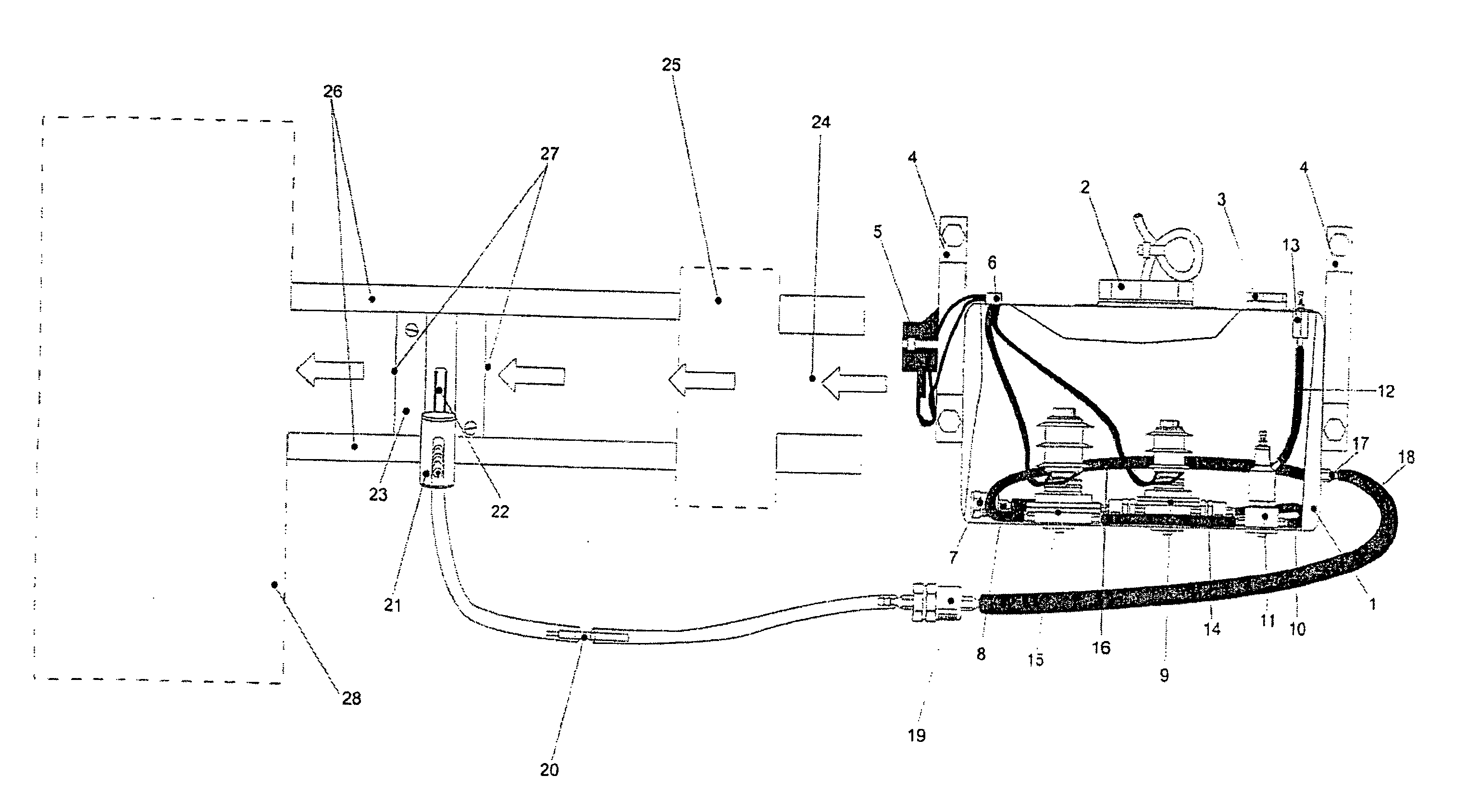
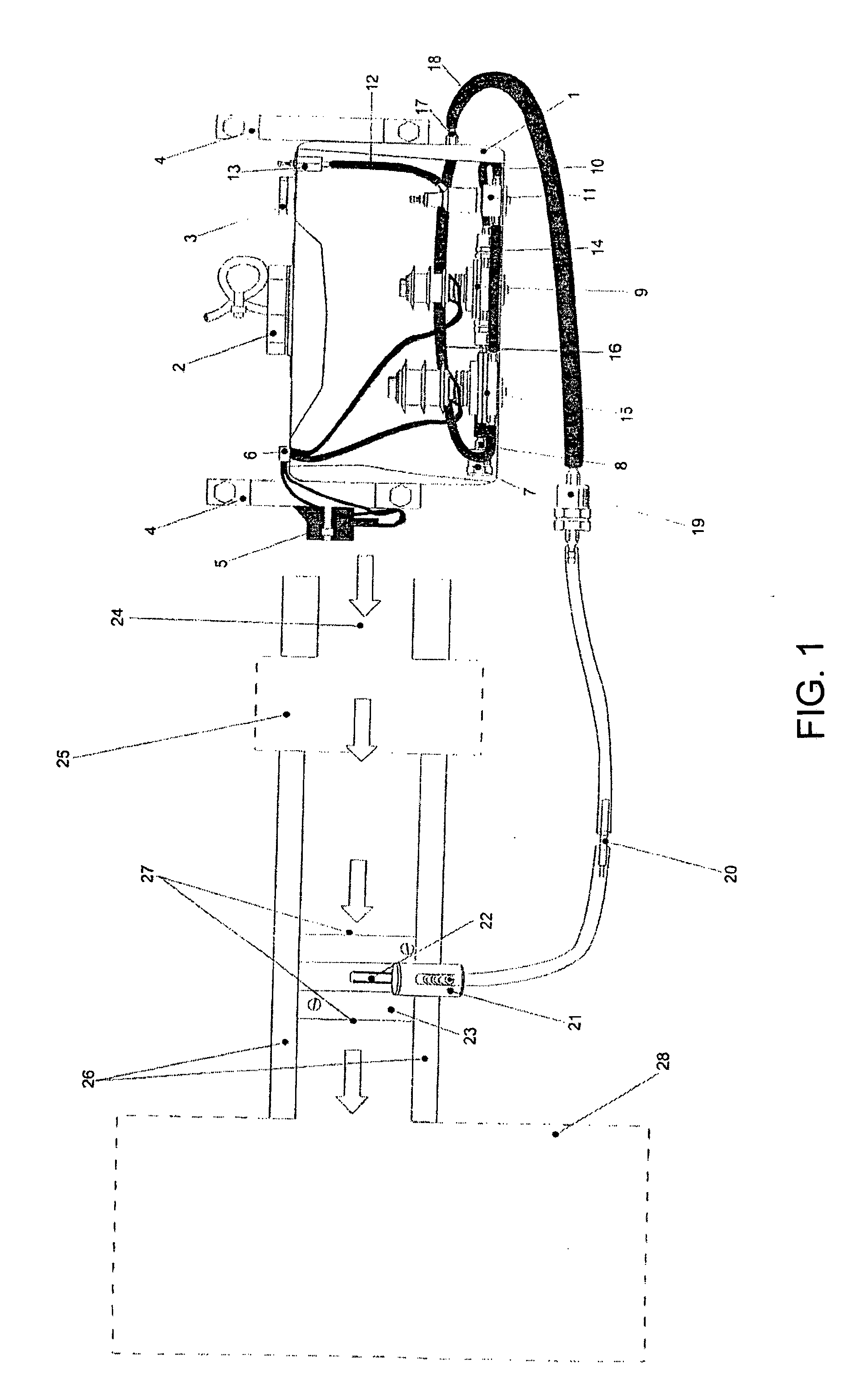
[0061]FIG. 1, represents the system to spray water according to a proportion from 1 to 5% of the fuel in the existing mixture and installed on board thereof, that includes a preferably-distilled water supply circuit including at least one water container deposit (1) with its supplying nozzle (2) and regulation stopper (3) mounted on a chassis support (4), characterized because in the interior and the base of this deposit (1) the elements placed in submerged conditions inside this fluid are placed operatively and linked to each other and externally commanded in automatic form by means of an electronic chip (5), constituted these elements by a filter (7) associated by means of connectors and water conduction sections (8) to a water flow propelling and aspiring measured electromagnetic pump (9), which on one side communicates through connectors and conduction pipe sections (10) with a water flow regulating valve (11) with its respective return of way with calibrated step of manual regulation (13), and over this at the same time communicates through connectors and pipe of water conduction (14) to a water flow safety valve of cutting (15), continuing the trajectory by a conduction pipe section (16) to water exit connector (17) of this deposit (1), passing later in external conditions to this deposit (1) by a pipe conduction section that accommodates in its interior a unidirectional valve (20) of this fluid finalizing in a lifting bridle (23) of a sprayer (22) with its drainage valve ready in the interior of the admission hose of the combustion air (26).
[0062]FIG. 2, represents the lifting bridle (23) of a sprayer (22) including a hollow cylindrical body, of adaptable outer diameter to the suction hose (26), in which ends have a woven mesh (27) to obtain a vortex effect of the air mass—water suctioned in the different motor settings (28).
Basic Principle of Operation
[0063]The water, preferably distilled, which contains the deposit, goes first through a filter element to continue its way and enter to a water flow measured pump electronically commanded by pulses of a chip with electronic command and control means, following its trajectory to a valve which regulates the water flow with respect to the suction of the motor admission, which has an adjustable return to alleviate the pressure of the pump, later this flow passes through a cutting valve that is driven by the contact of the motor, again the flow is filtered in the exterior of the deposit, continuing by a conduction pipe section in which in its trajectory point passes through an unidirectional valve (of non-return water flow), and finally arrives at a drainage valve and sprayer, which is incorporated into a bridle that is installed in the air combustion admission hose of the motors, which is in the air filter and the admission manifold.
[0064]In addition, by means of tests made by the own inventor were obtained important parameters that deserve to be mentioned, according to the application in motors fed by compressed natural gas (GNC), it was preferably used water spray in the motor according to a proportion from 0.2 to 1% of the fuel present in the mixture, obtaining a greater performance-thereof.
[0065]In agreement with all previously exposed and illustrated, it is easy to understand the advantages of practical order that offers this system; therefore the annexed claims cover the reach with the invention.

PUM

no PUM

Description & Claims & Application Information

We can also present the details of the Description, Claims and Application information to help users get a comprehensive understanding of the technical details of the patent, such as background art, summary of invention, brief description of drawings, description of embodiments, and other original content. On the other hand, users can also determine the specific scope of protection of the technology through the list of claims; as well as understand the changes in the life cycle of the technology with the presentation of the patent timeline. Login to view more.

Similar technology patents

Low-temperature gas generating agent

ActiveCN107586235ALarge amount of gasLow combustion temperatureExplosivesAmmonium sulfateBrown iron oxide
Owner:HUBEI INST OF AEROSPACE CHEMOTECH

Massage device and method of use thereof

InactiveUS20190046395A1Increased pressureSmall cross-sectional areaDevices for pressing relfex pointsRoller massageMassageVertebral column
Owner:ROUTLEDGE RAYMOND THOMAS

Plasma-assisted processing of gaseous media

InactiveUS6890495B1Low combustion temperatureIncrease rateGaseous chemical processesInternal combustion piston enginesBiomedical engineeringElectrode
Owner:ACCENSTUS PLC

Classification and recommendation of technical efficacy words

  • Increased pressure
  • Low combustion temperature
Why Eureka
Try Eureka