Condensate accumulation model for an engine heat exchanger

a heat exchanger and condensate accumulation technology, applied in the direction of machines/engines, combustion-air/fuel-air treatment, electric control, etc., can solve the problems of reducing the efficiency of the heat exchanger over time, affecting so as to improve the efficiency of the heat exchanger and reduce the cost of bypass lines , the effect of increasing the density

Active Publication Date: 2016-01-19
FORD GLOBAL TECH LLC
View PDF6 Cites 5 Cited by
  • Summary
  • Abstract
  • Description
  • Claims
  • Application Information

AI Technical Summary

Benefits of technology

[0002]Engine heat exchangers, such as charge air coolers and other coolers, may function to cool the temperature of charge air entering the intake manifold, providing charge air with higher density and thus increased engine power and improved fuel efficiency. Further, cooled charge air may lower combustion temperatures and aid in controlling certain engine emissions. However, under certain conditions, such as when the air in the heat exchanger is cooled below its dew point, condensate can form within the heat exchanger. The condensate may accumulate and then be swept to the engine, causing misfire and other problems; it can also reduce the effectiveness of the heat exchanger over time. Further, particularly in exhaust gas recirculation coolers which cool exhaust being recirculated back to the intake, acidic compounds may be present in the condensate, resulting in degradation to the cooler and / or downstream components.
[0005]In this way, the flow of EGR may be increased in response to condensation in an EGR cooler. In one example, the EGR flow may be increased when an estimated amount of accumulated condensate in the EGR cooler exceeds a threshold. The amount of accumulated condensate in the EGR cooler may be estimated based on both an amount of condensation that forms within the EGR cooler, as well as an amount of condensate that evaporates out of the EGR cooler over a given duration. By tracking both the amount of formed condensate as well as the amount of evaporated condensate, the amount of condensate that actually accumulates in the heat exchanger may be more accurately determined. Further, by adjusting EGR flow responsive to condensation in the cooler, condensate may be removed without utilizing a complicated bypass system, or in addition to such a bypass system.

Problems solved by technology

The condensate may accumulate and then be swept to the engine, causing misfire and other problems; it can also reduce the effectiveness of the heat exchanger over time.
Further, particularly in exhaust gas recirculation coolers which cool exhaust being recirculated back to the intake, acidic compounds may be present in the condensate, resulting in degradation to the cooler and / or downstream components.
However, such bypass lines may be expensive and increase the complexity of the engine control system strategy.
Further, it may be difficult to accurately predict when condensation may form, resulting in unnecessary bypass of the air and increased temperature and decreased density of the charge air.

Method used


Image

  • Condensate accumulation model for an engine heat exchanger
  • Condensate accumulation model for an engine heat exchanger
  • Condensate accumulation model for an engine heat exchanger

Examples


Embodiment Construction

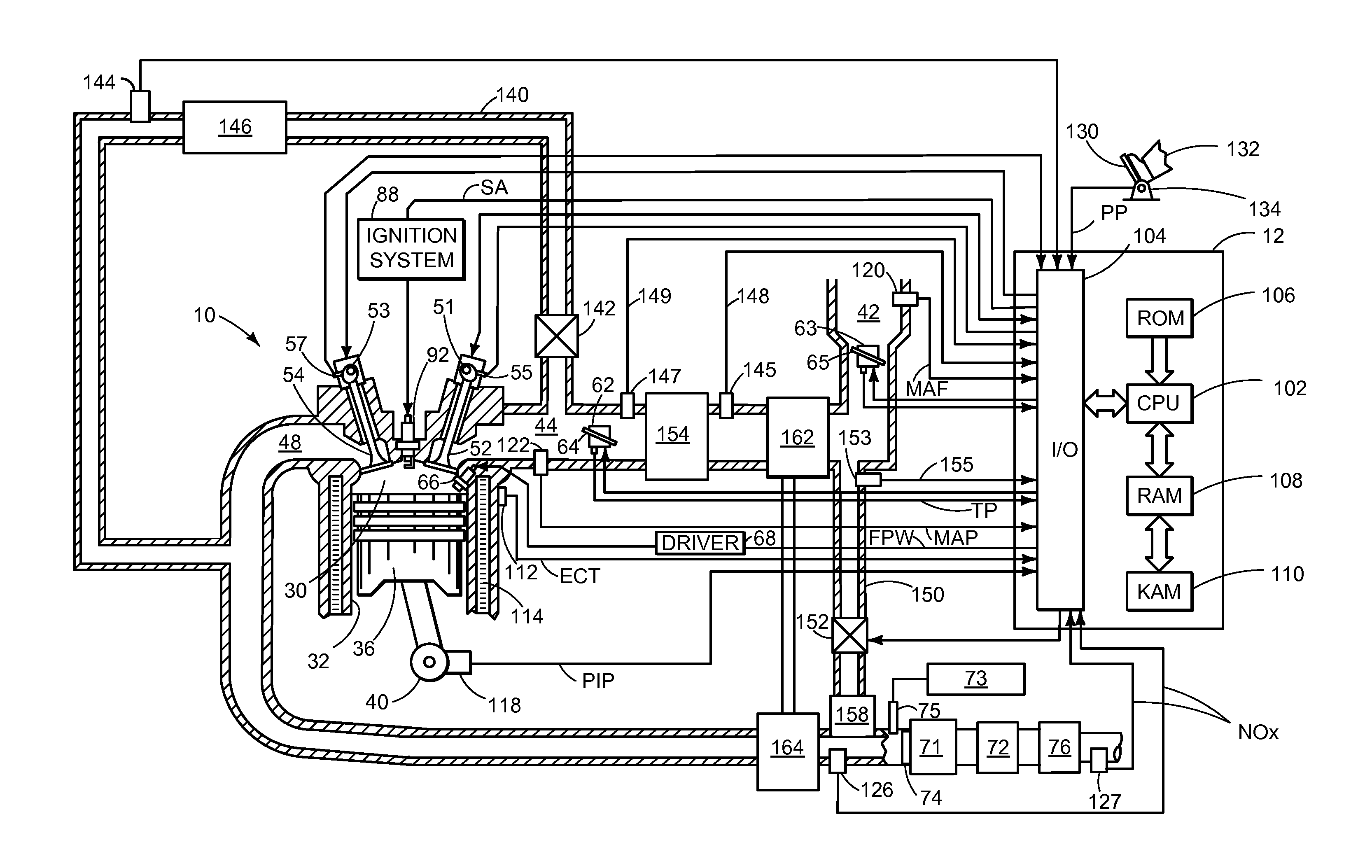
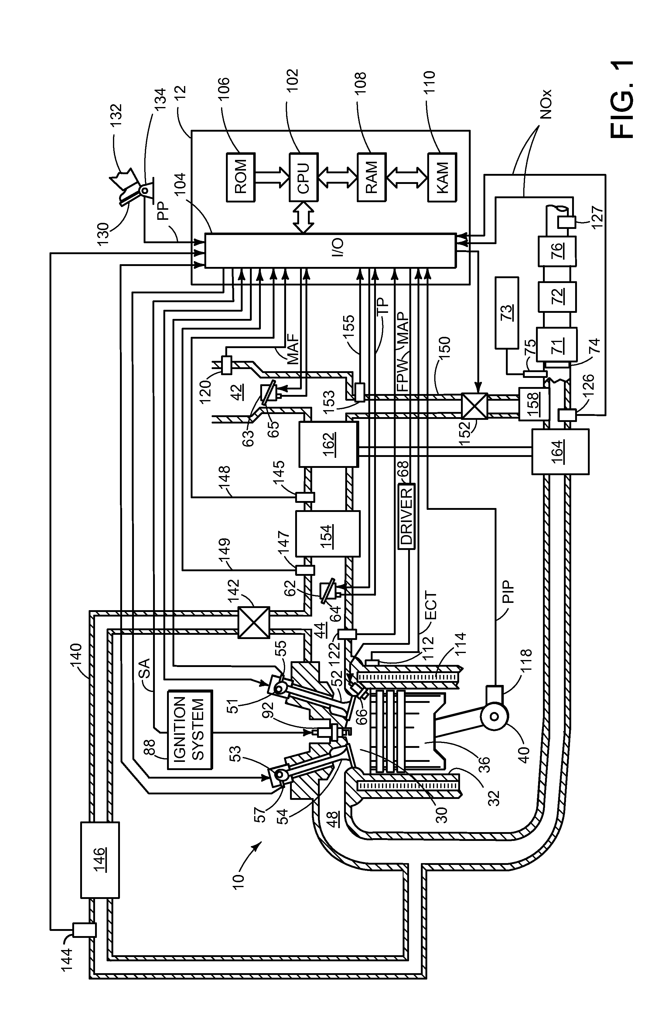
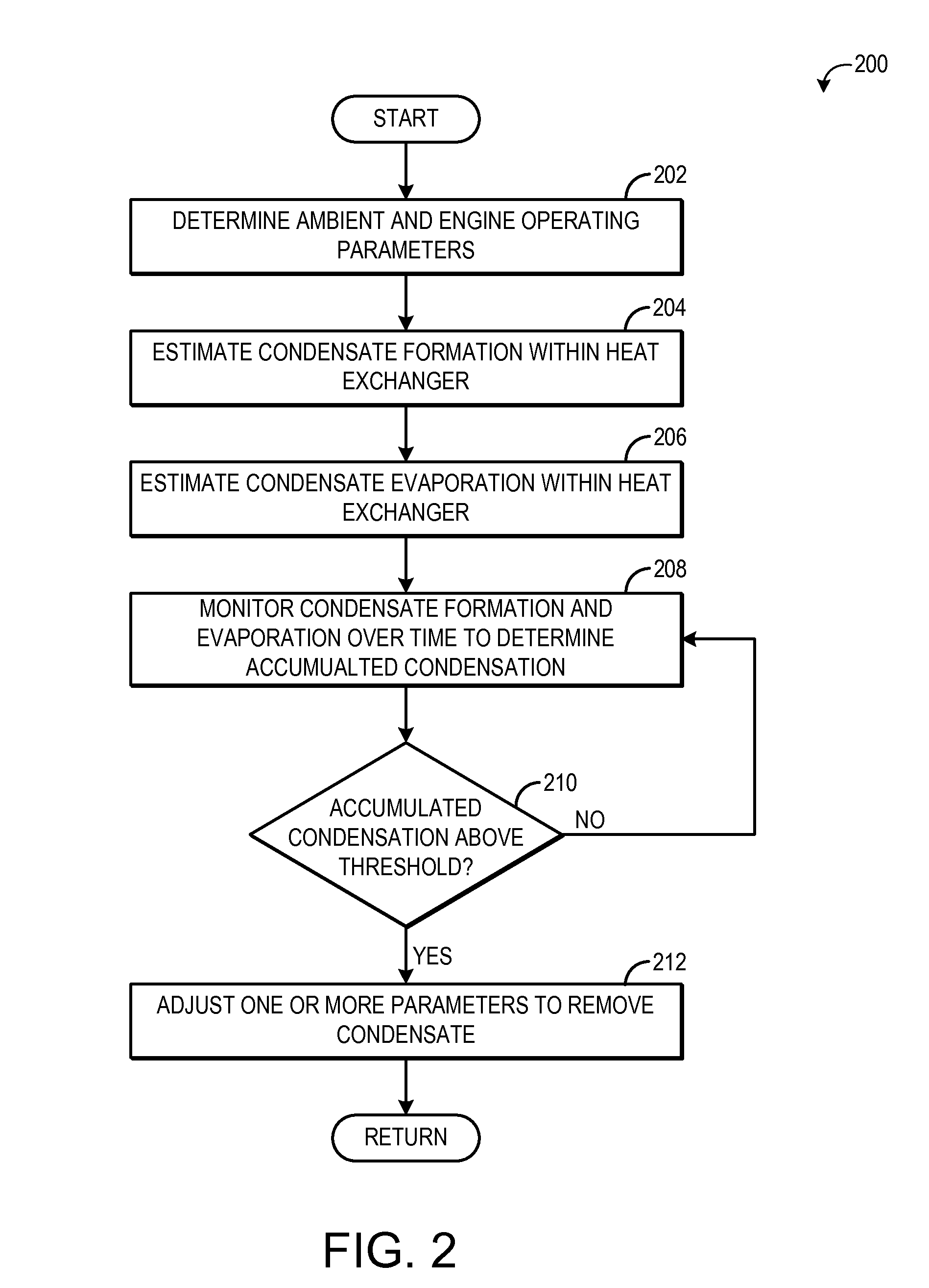
[0013]Engine heat exchangers, such as EGR coolers and charge air coolers, may accumulate condensate under some conditions. The accumulated condensate may be swept to the engine, where if it is present in large amounts, may cause misfire and other combustion issues or component damage. In order to prevent the accumulation of condensate within an engine heat exchanger, the amount of formed and evaporated condensate within the heat exchanger may be tracked using a condensation model. The condensation model may output formed and evaporated condensate based on speed and load dependent operating parameters, such as EGR rate, boost pressure, and mass air flow. If the condensate in the heat exchanger accumulates to a threshold level, an engine actuator may be adjusted to remove the condensate from the heat exchanger. FIG. 1 illustrates an engine including multiple heat exchangers and a controller configured to execute the methods illustrated in FIGS. 2-5.

[0014]Referring now to FIG. 1, it sh...


PUM


Abstract

Embodiments for controlling condensate in an engine heat exchanger are disclosed. In one example, a method for an engine comprises increasing exhaust gas recirculation (EGR) flow responsive to condensation in an EGR cooler. In this way, condensate in the EGR cooler may be controlled via modulation of EGR flow.

Description

FIELD[0001]The present disclosure relates to internal combustion engines.BACKGROUND AND SUMMARY[0002]Engine heat exchangers, such as charge air coolers and other coolers, may function to cool the temperature of charge air entering the intake manifold, providing charge air with higher density and thus increased engine power and improved fuel efficiency. Further, cooled charge air may lower combustion temperatures and aid in controlling certain engine emissions. However, under certain conditions, such as when the air in the heat exchanger is cooled below its dew point, condensate can form within the heat exchanger. The condensate may accumulate and then be swept to the engine, causing misfire and other problems; it can also reduce the effectiveness of the heat exchanger over time. Further, particularly in exhaust gas recirculation coolers which cool exhaust being recirculated back to the intake, acidic compounds may be present in the condensate, resulting in degradation to the cooler ...

Claims


Application Information

Patent Timeline
Patent Type & Authority Patents(United States)
IPC IPC(8): F02M25/07F02D41/04F02D21/08F02B29/04F02M35/08F02D13/02F02D41/00F02D41/14
CPCF02B29/0468F02M25/0701F02M25/0707F02M25/0709F02M25/0732F02M35/088F02D41/0055F02D21/08F02M25/0753F02D13/0203F02D2041/1472F02D41/0062F02D2200/0418Y02T10/146Y02T10/47F02M26/05F02M26/06F02M26/50F02M26/24F02M26/45Y02T10/12Y02T10/40
Inventor FULTON, BRIEN LLOYDSTYLES, DANIEL JOSEPH
Owner FORD GLOBAL TECH LLC
Why Eureka
Try Eureka