
Method for preparing membrane electrode assembly using low-temperature transfer method, membrane electrode assembly prepared thereby, and fuel cell using the same

a technology of membrane electrodes and electrode assemblies, which is applied in the manufacture of final products, cell components, electrochemical generators, etc., can solve the problem that the catalyst layer may not be well transferred

Inactive Publication Date: 2013-08-27
KOREA INST OF SCI & TECH
View PDF10 Cites 4 Cited by
  • Summary
  • Abstract
  • Description
  • Claims
  • Application Information

AI Technical Summary

Benefits of technology

The patent describes a method for making membrane electrode assemblies (MEAs) using a low-temperature transfer method instead of a high-temperature transfer method. The low-temperature method prevents the formation of a thin skin layer with high resistance that can occur when using a high-temperature method. This results in better performance and lower resistance to material transport and electrical resistance for the resulting MEAs. Additionally, the method allows for the large-scale production of MEAs.

Problems solved by technology

If the temperature is lower than about 180° C., the catalyst layer may not be well transferred.

Method used


Image

  • Method for preparing membrane electrode assembly using low-temperature transfer method, membrane electrode assembly prepared thereby, and fuel cell using the same
  • Method for preparing membrane electrode assembly using low-temperature transfer method, membrane electrode assembly prepared thereby, and fuel cell using the same
  • Method for preparing membrane electrode assembly using low-temperature transfer method, membrane electrode assembly prepared thereby, and fuel cell using the same

Examples


example 1

MEA Prepared by Low-temperature Transfer Method using Transfer Substrate on which Outer Ionomer Layer and Binder-free Carbon Layer are Formed (Denoted as MEA 603 in Performance Measurement and as MEA 703 in Impedance Measurement)>

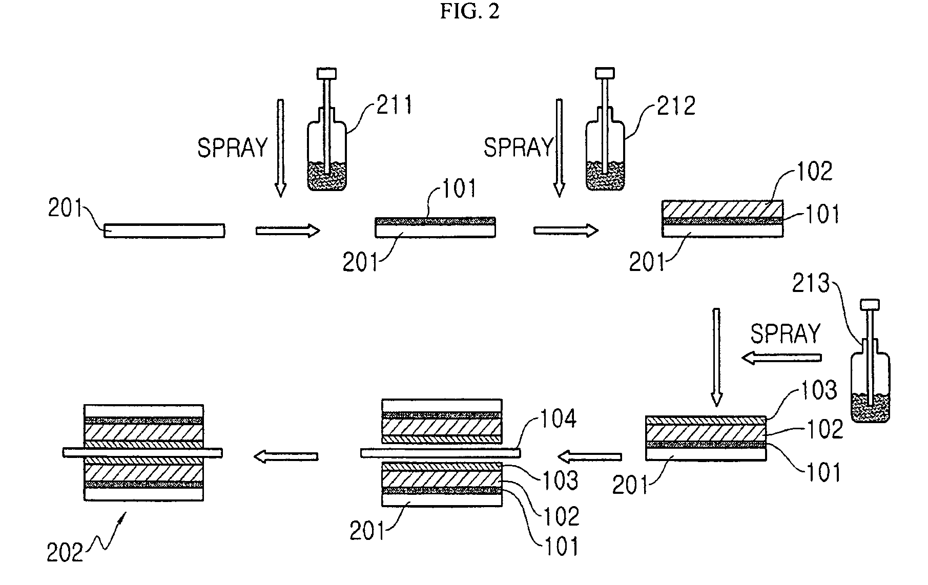
[0101]A catalyst slurry is prepared in the same manner as Comparative Example 1. A binder-free carbon slurry is prepared by dispersing carbon powder (Vulcan XC-72R, Cabot Co.) and IPA at a weight ratio of 1:1000. The prepared binder-free carbon slurry is applied on a transfer substrate by spraying and the transfer substrate is dried in an oven at 80° C. (see FIG. 2).

[0102]The catalyst slurry is applied on the transfer substrate on which a binder-free carbon layer is formed, and outer ionomer is further applied at 0.1 mg / cm2 as in Comparative Example 3. Thereafter, the transfer substrate is completely dried.

[0103]Thus prepared transfer substrate on which the binder-free carbon layer, the catalyst layer and the outer ionomer layer are formed is hot-...

example 2

MEA Prepared by Slurry Drying Method using Transfer Substrate and Electrode Frame (Denoted as MEA 604 in Performance Measurement)>

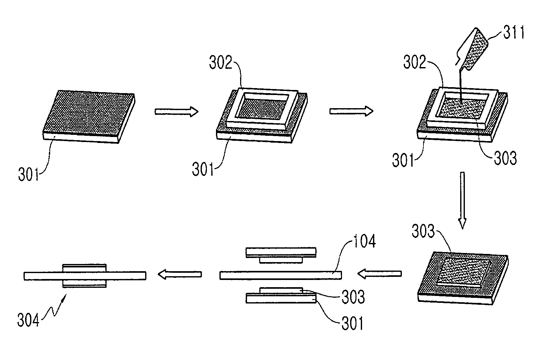
[0105]An electrode frame with a size corresponding to the area of the electrode is placed on a transfer substrate having the binder-free carbon layer identical to that prepared in Example 1. A catalyst slurry identical to that prepared in Comparative Example 1 is poured in the electrode frame and then dried (see FIG. 3).

[0106]The amount of catalyst is set as 3 mg / cm2 for both the anode and the cathode on the basis of the metal catalyst.

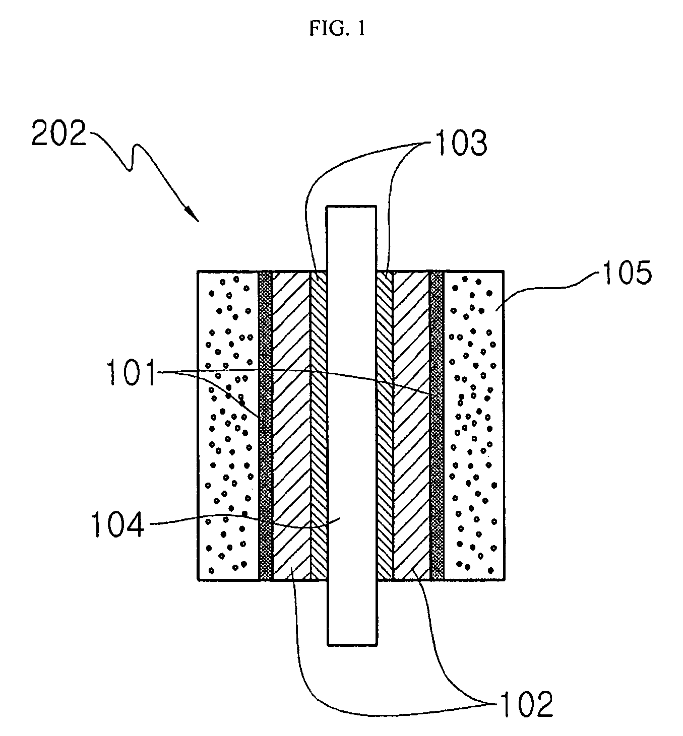
[0107]After drying, the electrode frame is removed, and the catalyst layer formed on the transfer substrate having the binder-free carbon layer is transferred from the transfer substrate to a PEM by pressing at 140° C. and 8 MPa for 8 minutes after placing the anode and cathode transfer substrates on either side of the PEM.

[0108]An MEA is obtained. Gas diffusion layers [TGPH-060 carbon paper (Toray Co.)] are overl...


PUM

PropertyMeasurementUnit
thicknessaaaaaaaaaa
particle sizeaaaaaaaaaa
porosityaaaaaaaaaa

Abstract

A membrane-electrode assembly (MEA) is prepared by a low-temperature transfer method. A binder-free carbon layer is formed on a transfer substrate so as to avoid decreased performance due to the formation of a skin layer caused by the interfacial segregation of the ionomer or binder.

Description

[0001]This application claims benefit of Serial No. 10-2008-0023456, filed Mar. 13, 2008 in South Korea and which application(s) are incorporated herein by reference. A claim of priority to all, to the extent appropriate is made.BACKGROUND[0002]1. Field[0003]This disclosure relates to a method for preparing a membrane electrode assembly (MEA) using a low-temperature transfer method, an MEA prepared thereby, and a fuel cell using the same.[0004]2. Background of the Related Art[0005]A polymer electrolyte membrane fuel cell (PEMFC) generates electricity through electrochemical reaction of fuel such as hydrogen, methanol, etc. (on the anode side) and air (on the cathode side). Since the PEMFC may operate continuously for a long period of time as long as the fuel is supplied, it may have advantages over the secondary cells that it does not have problems of limited capacity, inconvenience due to charging, or the like.[0006]One of the key elements of PEMFC is a membrane electrode assembly ...

Claims


Application Information

Patent Timeline
Patent Type & Authority Patents(United States)
IPC IPC(8): H01M8/00
CPCH01M4/8605H01M4/8807H01M4/8817H01M4/8828H01M4/8892H01M8/1004H01M2008/1095Y02E60/521Y02E60/50Y02P70/50B82Y30/00H01M4/86H01M4/88
Inventor KIM, SOO-KILCHO, JAE HYUNGHA, HEUNG YONGOH, IN HWANLIM, TAE HOONNAM, SUK-WOOHONG, SEONG AHN
Owner KOREA INST OF SCI & TECH
Learn More