Film forming apparatus, film forming method and storage medium

a film forming and film forming technology, applied in the field of film forming technique, can solve the problems of deterioration in film quality, increase in film thickness on the gas supply side, and decrease in film thickness on the gas exhaust side, so as to improve in-plane uniformity in film thickness, shorten the time, and reduce the volume of the gas shower head filled.

Active Publication Date: 2013-09-24
TOKYO ELECTRON LTD
View PDF57 Cites 34 Cited by
  • Summary
  • Abstract
  • Description
  • Claims
  • Application Information

AI Technical Summary

Benefits of technology

[0029]In accordance with the aspects of the present invention, a first processing gas and a second processing gas are alternately supplied from a gas shower head facing a substrate, to form a film made of reaction products of the processing gases on the substrate. Accordingly, it is possible to improve in-plane uniformity in film thickness and film quality, compared to a side flow manner. Further, the gas shower head is divided into a central region and a peripheral region and the first processing gas and the second processing gas are alternately supplied from the central region. Accordingly, it is possible to reduce the volume of the gas shower head filled with the processing gas and shortening time required for replacement of the processing gas in the gas shower head. Further, during replacement of process atmosphere, a purge gas is additionally discharged from the peripheral region of the gas shower head. Accordingly, it is possible to shorten replacement time of the processing gas and improve throughput. Further, the volume of processing gas filled in the gas shower head is small. Accordingly, it is possible to reduce the amount of discharged processing gas during every replacement of the processing gas.

Problems solved by technology

Since the above-mentioned gas is rarely decomposed at a low temperature, when a film is formed at a low temperature, impurities infiltrate into the film to cause deterioration in film quality.
Thus, it may cause deterioration in in-plane uniformity of film thickness, that is, an increase in film thickness on the gas supply side and a decrease in film thickness on the gas exhaust side.
Further, gas of a high-k dielectric material is expensive.
Further, for example, when an ozone gas is supplied for a short period of time for the purpose of improving throughput, an oxidation power of ozone gas becomes weakened due to consumption of the ozone gas as it goes farther from an ozone gas supply source.
Further, as shown in FIG. 16C, the processing gas flowing in the vicinity of the substrate 101 takes part in the reaction, whereas the processing gas flowing in a region apart from the substrate 101 is discharged, thus causing low film formation efficiency (film formation ratio) and waste of expensive processing gas.
Also, a long period of time is necessary to obtain a desired film thickness.
Further, the high-speed rotation valve 106 is expensive and the manufacturing cost of the film forming apparatus 100 is high.
However, this gas shower head has a large size, and it is necessary to replace the atmosphere inside the gas shower head in every switching of the processing gas in order to alternately supply the processing gases plural times, as mentioned above.
As a result, the amount of processing gas wasted increases.
Further, in the gas shower head, the volume of the replaced gas (the volume of the gas shower head) is large and it requires a long period of time in gas replacement, thus causing deterioration in throughput.
Further, there is no established dry cleaning method for removing deposits in the chamber produced by the TEMAZ gas serving as a source for the high-k dielectric material and a manual wet cleaning method is employed instead.
This leads to non-uniform flow of the processing gas on the substrate 210 and variations in film thickness.
Accordingly, there is another problem that it is impossible to supply a large amount of purge gas in the film forming apparatus 200.
In this case, the processing gases or reaction products may be deposited on the bellows and the bellows may be damaged upon contraction to cause leakage of the processing chamber 201.
However, in the film forming apparatus 220, the flow rate of purge gas cannot be greatly increased due to the small diameter of the holes 211, and it takes a long time in gas replacement when one of the film forming gas and the oxidizing gas is switched by the other, causing deterioration in throughput.

Method used


Image

  • Film forming apparatus, film forming method and storage medium
  • Film forming apparatus, film forming method and storage medium
  • Film forming apparatus, film forming method and storage medium

Examples


example 1

[0092]Next, experiments performed to confirm effects of the present invention will be described.

[0093]In the experiments, film formation was performed under the following process conditions and properties such as film thickness were measured.

[0094](Process Conditions)

[0095]Gas type (film forming gas / oxidizing gas): TEMAZ gas / ozone gas=10, 25, 50, 100 (mg / min) / 200 (g / Nm3)

[0096]Process time (film formation / oxidation): 1.5 / 3 sec

[0097]Process temperature: 250° C.

[0098]Gas replacement time (film formation / oxidation): 5 / 5 sec

[0099]Number of times film formation / oxidation is repeated: 100 times

experimental example 1

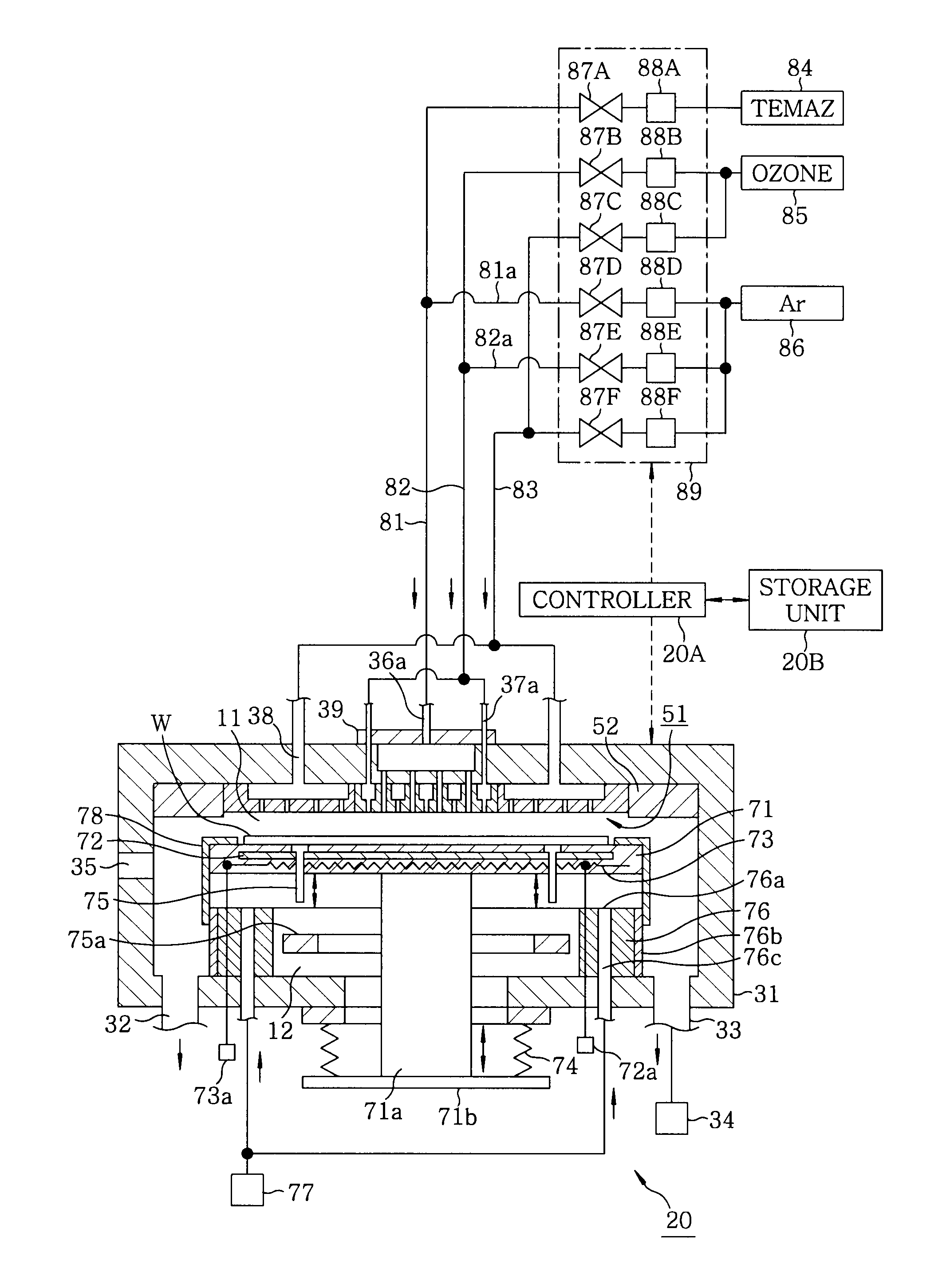
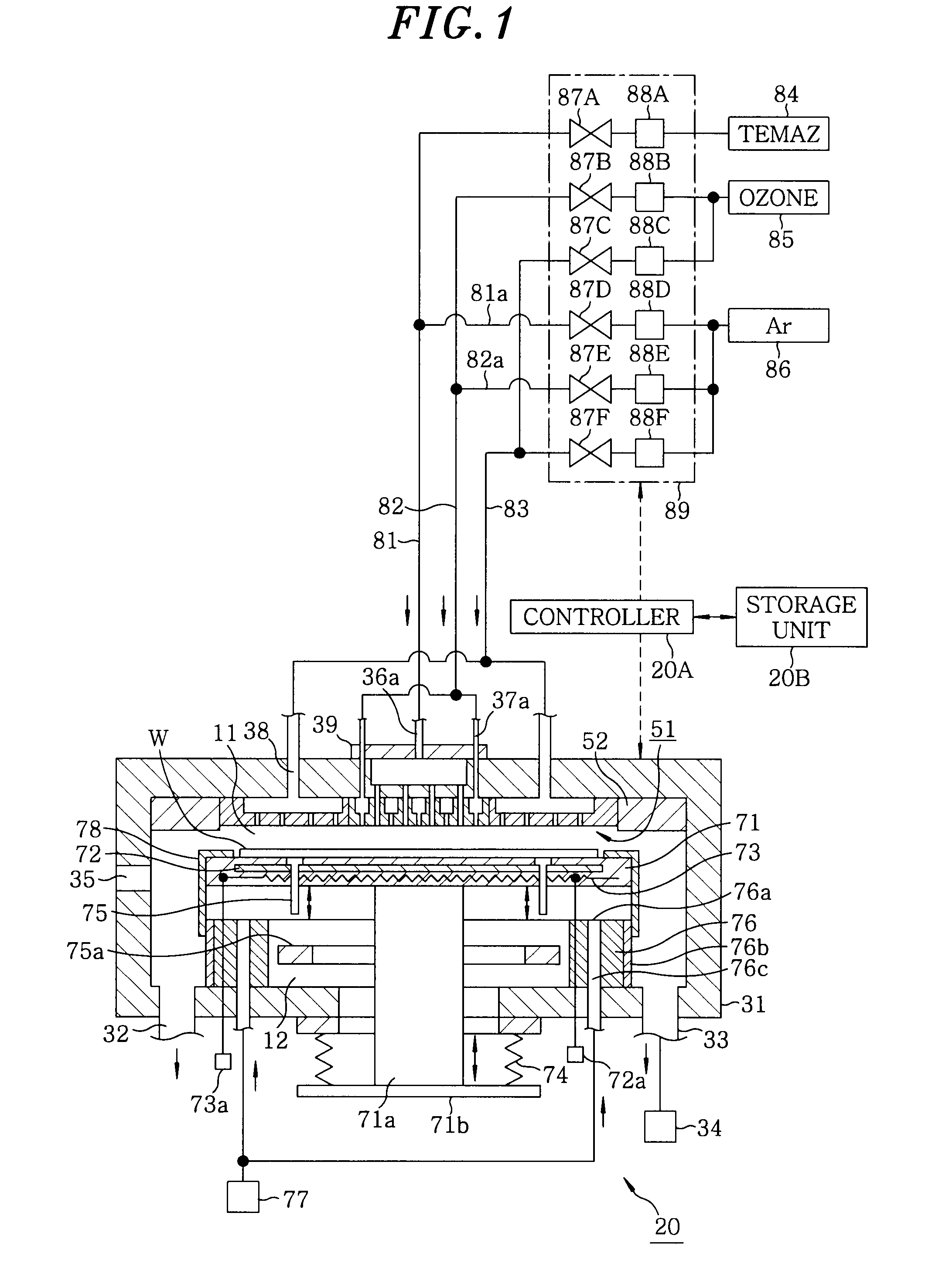
[0100]The experiment was carried out in the film forming apparatus 20 including the gas shower head 51.

example 2

[0104]Next, in the same manner as mentioned above, experiments were carried out under the following conditions.

[0105](Process Conditions)

[0106]Process time (film formation / oxidation): 1.5 / 3 sec

[0107]Gas replacement time (film formation / oxidation): 5 / 5 sec

[0108]Number of times film formation / oxidation is repeated: 100


PUM

PropertyMeasurementUnit
temperatureaaaaaaaaaa
distanceaaaaaaaaaa

Abstract

A film forming apparatus includes a processing chamber, and a mounting table disposed in the processing chamber to mount a substrate thereon. The film forming apparatus further includes a gas shower head having gas supply holes and including a central region facing a central portion of the substrate and a peripheral region facing a peripheral portion of the substrate, a first processing gas supply unit for supplying a first processing gas to the central region, a second processing gas supply unit for supplying a second processing gas to the central region, an energy supply unit for supplying energy to react the first processing gas with the second processing gas on the substrate, and a purge gas supply unit for supplying a purge gas to the central region and the peripheral region when one of the first and the second processing gas is switched by the other.

Description

CROSS-REFERENCE TO RELATED APPLICATION(S)[0001]This application claims the benefit of Japanese Patent Application No. 2007-0082533, filed on Mar. 27, 2007, which is hereby incorporated by reference herein in its entirety.FIELD OF THE INVENTION[0002]The present invention relates to a film forming technique in which a first processing gas and a second processing gas are alternately supplied plural times to form a film made of reaction products of the processing gases on a substrate.BACKGROUND OF THE INVENTION[0003]As a film forming method in a semiconductor fabrication process, there is known a method including adsorbing a first processing gas on the surface of a substrate, replacing the first processing gas with a second processing gas, reacting the two gases with each other to form one or more atomic or molecular layers, and repeating this cycle plural times to deposit these layers. This method is referred to as atomic layer deposition (ALD), molecular layer deposition (MLD) or the ...

Claims


Application Information

Patent Timeline
Patent Type & Authority Patents(United States)
IPC IPC(8): C23C16/455G05B15/00H01L21/306C23F1/00C23C16/52G06F17/00C23C16/06C23C16/22
CPCC23C16/45521C23C16/45565H01L21/31641C23C16/4586H01L21/3141C23C16/45574H01L21/0228H01L21/02189H01L21/20H01L21/31H01L21/02
Inventor TAKAGI, TOSHIO
Owner TOKYO ELECTRON LTD
Why Eureka
Try Eureka